52 | Chapter 7 “1+N” System |
7.2.2 Cabinet Installation
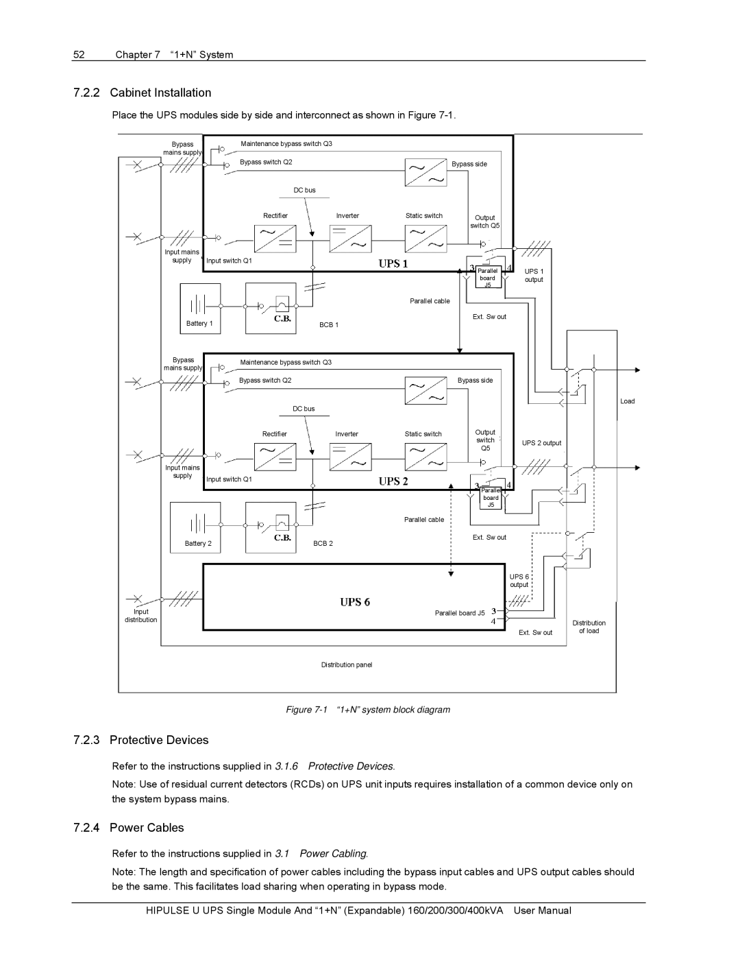
Place the UPS modules side by side and interconnect as shown in Figure
Bypass
mains supply
Input mains
supply
Maintenance bypass switch Q3
Bypass switch Q2
DC bus
Rectifier | Inverter |
Input switch Q1
| Bypass side |
Static switch | Output |
switch Q5
Parallel | UPS 1 |
board | output |
J5 |
|
Parallel cable |
Battery 1 | BCB 1 | ||
Bypass | Maintenance bypass switch Q3 | ||
mains supply | |||
|
| ||
| Bypass switch Q2 |
| |
|
| DC bus | |
| Rectifier | Inverter | |
Input mains |
|
| |
supply | Input switch Q1 |
| |
|
| ||
Battery 2 | BCB 2 |
Input
distribution
Ext. Sw out
| Bypass side |
|
|
| Load |
Static switch | Output |
|
| switch | UPS 2 output |
| Q5 | |
|
|
Parallel |
board |
J5 |
Parallel cable |
Ext. Sw out
UPS 6 output
Parallel board J5
| Distribution |
Ext. Sw out | of load |
Distribution panel
Figure 7-1 “1+N” system block diagram
7.2.3 Protective Devices
Refer to the instructions supplied in 3.1.6 Protective Devices.
Note: Use of residual current detectors (RCDs) on UPS unit inputs requires installation of a common device only on the system bypass mains.
7.2.4 Power Cables
Refer to the instructions supplied in 3.1 Power Cabling.
Note: The length and specification of power cables including the bypass input cables and UPS output cables should be the same. This facilitates load sharing when operating in bypass mode.
HIPULSE U UPS Single Module And “1+N” (Expandable) 160/200/300/400kVA User Manual