20 | Chapter 3 Electrical Installation |
3.3 Control Cabling
3.3.1 Monitoring Board Ports
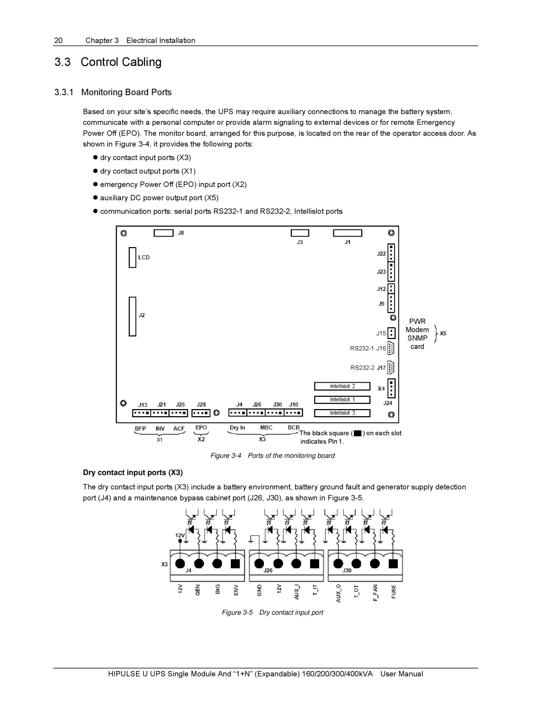
Based on your site’s specific needs, the UPS may require auxiliary connections to manage the battery system, communicate with a personal computer or provide alarm signaling to external devices or for remote Emergency Power Off (EPO). The monitor board, arranged for this purpose, is located on the rear of the operator access door. As shown in Figure
zdry contact input ports (X3)
zdry contact output ports (X1)
zemergency Power Off (EPO) input port (X2)
zauxiliary DC power output port (X5)
zcommunication ports: serial ports
X1
Dry contact input ports (X3)
| PWR |
J15 | ModemODEM/ |
卡电 | |
| SNMP |
源 | |
card | |
|
The black square ( 
 ) on each slot indicates Pin 1.
Figure 3-4 Ports of the monitoring board
The dry contact input ports (X3) include a battery environment, battery ground fault and generator supply detection port (J4) and a maintenance bypass cabinet port (J26, J30), as shown in Figure
Figure 3-5 Dry contact input port
HIPULSE U UPS Single Module And “1+N” (Expandable) 160/200/300/400kVA User Manual