28 | Chapter 4 | Operator Control And Display Panel | |||||
|
|
|
|
|
|
|
|
|
| LED |
|
| State |
| Description |
|
|
|
|
| Steady green |
| UPS output ON and normal |
|
| Load LED |
|
| Steady red |
| UPS output ON and overloaded |
|
|
|
|
| OFF |
| UPS output OFF |
|
| Alarm LED |
|
| Steady green |
| Normal operation |
|
|
|
| Steady yellow |
| UPS warning (for example, AC input failure) | |
|
| (STATUS) |
|
|
| ||
|
|
|
| Steady red |
| UPS fault (for example, fuse or hardware failure) | |
|
|
|
|
|
| ||
4.1.2 Buzzer
The operator control and display panel provides a buzzer. UPS activity is accompanied by the following sounds.
| Table | |
|
|
|
Single beep |
| Direct access key acknowledgement |
One beep per second |
| UPS warning. For example, AC input failure |
Continuous beep |
| Fault. For example, fuse or hardware failure |
4.1.3 Control Buttons
The operator control and display panel provides four control buttons, as described in Table
|
|
| Table |
|
|
|
|
| Control button |
| Description |
| INVERTER ON |
| Pushing this button turns on the inverter. |
|
| Note: If the inverter is not ready, pushing this button cannot turn on the UPS | |
|
|
| |
|
|
| |
| INVERTER OFF | During UPS operation, pushing this button turns off the inverter and transfers the load to the bypass | |
| FAULT CLEAR |
| In case the UPS shuts down due to fault, after eliminating the alarm conditions, pushing this button clears |
|
| the fault | |
|
|
| |
|
|
|
|
| SILENCE |
| When an alarm is active, pushing this button silences the audible alarm. When a new alarm occurs |
|
| afterwards, the buzzer will give audible alarm again. When there is no audible alarm, pushing this button | |
| ON/OFF |
| |
|
| initiates the audible alrm test | |
|
|
| |
|
|
|
|
![]() Note
Note
To activate the above control buttons, you are required to press and hold the buttons for approximately 2 seconds until a beeping sound is heard.
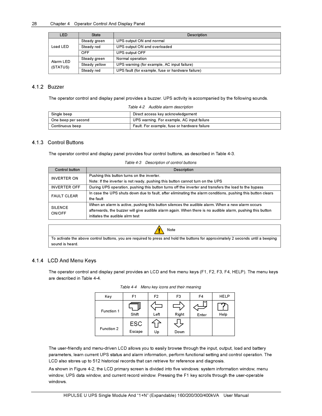
4.1.4 LCD And Menu Keys
The operator control and display panel provides an LCD and five menu keys (F1, F2, F3, F4, HELP). The menu keys are described in Table
Table
Key | F1 | F2 | F3 | F4 | HELP | |
Function 1 |
|
|
|
| ? | |
Shift | Left | Right | Enter | Help | ||
| ||||||
Function 2 | ESC |
|
|
|
| |
Escape | Up | Down |
|
| ||
|
|
|
The
As shown in Figure
HIPULSE U UPS Single Module And “1+N” (Expandable) 160/200/300/400kVA User Manual