Oxymitter 4000 Oxygen Transmitter
Page
Summary
Effective May 31, 2006 Rev
Highlights of Changes
Table of Contents
Troubleshooting
Configuration of Oxymitter 4000 with LOI
Maintenance and Service
Startup and Operation of Oxymitter 4000 with LOI
Optional Accessories
Replacement Parts
Safety Data Appendix B Return of Material
Appendix a
TOC-4
Read this page Before Proceeding
Oxymitter Oxygen Transmitters
Essential Instructions
Page
Section Introduction
Definitions
Symbols
Preface
Oxymitter
What YOU Need to Know
Oxymitter 4000 with
Oxymitter 4000 with Remote
Oxymitter 4000 with Remote Electronics Imps
Oxymitter 4000 with Remote Electronics SPS 4001B
Use this Quick Start Guide if
Can YOU USE the Quick Start GUIDE?
Quick Start Guide for Oxymitter 4000 Systems
Performing a Manual Calibration with a Membrane Keypad
Quick Reference Guide Manual Calibration Instructions
Technical Support Hotline
Hart Communicator Fast KEY Sequences
Scope
Description and Specifications
Component Checklist System Overview
Typical System Package IM-106-340, Rev May
System Description
System Configuration System Features
Imps
Oxymitter AutoCalibration System Options
Membrane Keypad
Oxymitter
Model 751 LCD Display Panel
Handling the Oxymitter
Oxymitter Hart Communications AMS Application
System Considerations
Imps 4000* Multiprobe
Standard
Autocalibration
Option
Inst
Operation
Imps 4000 Optional SPS 4001B Optional
Mounting
Ceramic Diffusion Assembly
Model 751 Remote Powered Loop LCD Display
Probe Options
Diffusion Elements
Abrasive Shield Assembly
Snubber Diffusion Assembly
Cup-Type Diffusion Assembly
14. Abrasive Shield Assembly
Oxymitter Specifications
Specifications
Oxymitter
IM-106-340, Rev .0 May Product Matrix
Code Language
IM-106-340, Rev .0 May Calibration Components
Section Installation
Selecting Location
Mechanical Installation
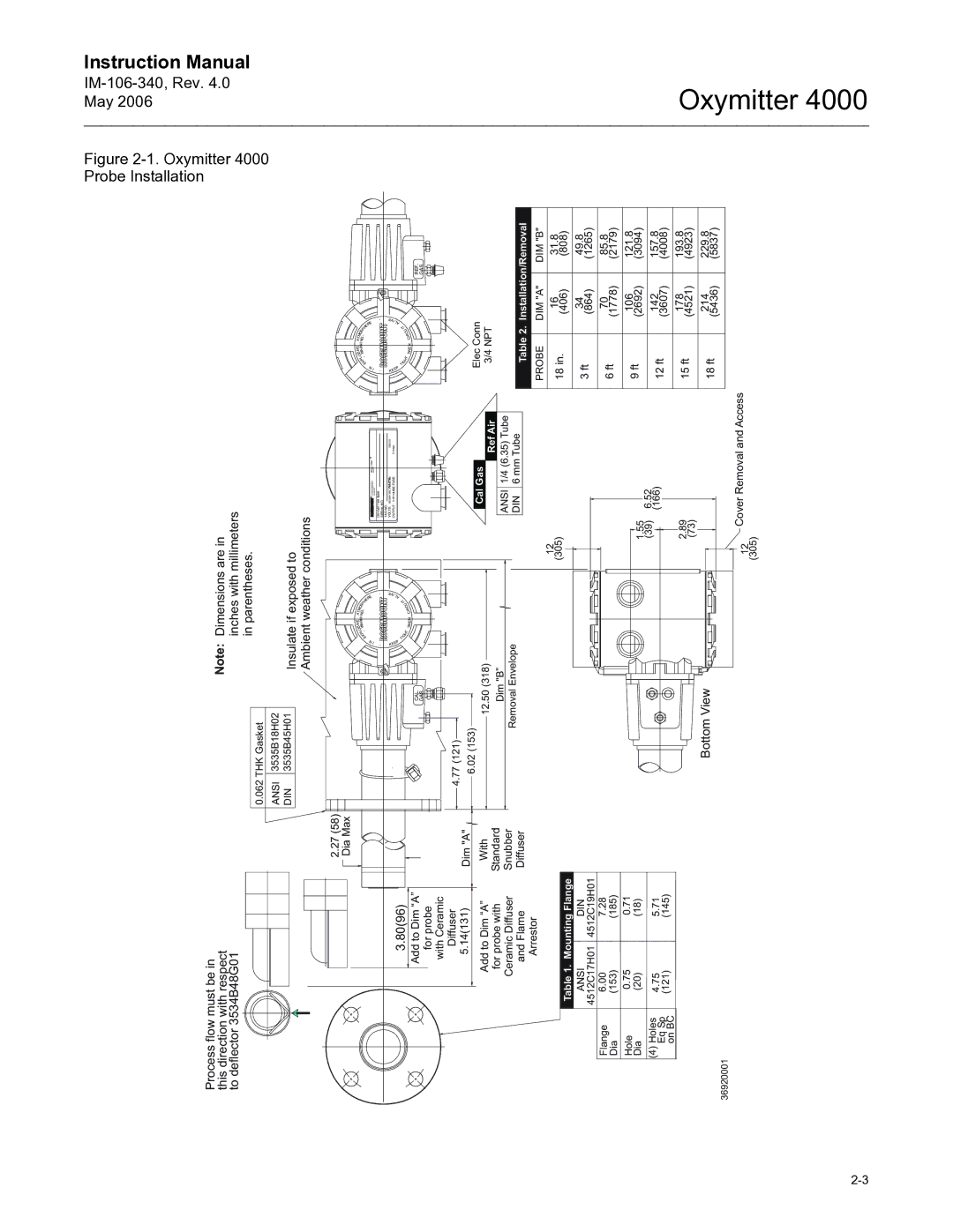
Probe Installation
Oxymitter 4000 Probe Installation
Oxymitter Remote Electronics Installation
Oxymitter 4000 with Abrasive Shield
Adaptor Plate Outline
Oxymitter 4000 Adapter Plate Installation
Oxymitter 4000 Abrasive Shield Bracing Installation
Orienting Optional Vee DeflectorGas Flow
Remote Electronics Installation
For Oxymitter 4000 with Integral Electronics
Electrical Installation with Integral Electronics
Oxymitter
Integral Electronics with Remote Imps
Integral Electronics Without SPS 4001B
Integral Electronics with Remote SPS 4001B
For Oxymitter 4000 with Remote Electronics
Electrical Installation with Remote Electronics
Oxymitter
Probe
Pneumatic Installation
Install Interconnecting Cable
Reference Air Package
Calibration Gas
11. Air Set, Plant Air Connection
Imps 4000 Connections SPS 4001B Connections
Mechanical Installation Terminal Block Wiring
Configuration of Oxymitter 4000 with Membrane Keypad
Verify Installation
SW1 Setting
Oxymitter 4000 Configuration
SW2 Setting
OFF
Read O2 Concentration
Logic I/O
Alarm
Calibration Handshake Signal
Recommended Configuration
MA Signal Upon Critical Alarm
Calibration
Configuration of Oxymitter 4000 with LOI
Electronics Housing Terminals with LOI
Model 751. The loop-driven LCD display
Defaults Oxymitter 4000 with LOI IM-106-340, Rev .0 May
Calibration Handshake Signal
Recommended
Configuration
Recommended Configuration
Startup and Operation Oxymitter 4000 with Membrane Keypad
Power UP
Startup Display
Operating Display
Overview
Operation
Calibration Recommended LED
Test Points
CAL
Model 751 Remote Powered Loop LCD Display Optional
Keys
Oxymitter
LOI
Startup and Operation of Oxymitter 4000 with LOI
O2 Ø.ØØ% LK warm up 367dgC
Overview Lockout
LOI Features
LOI KEY Designations LOI Menu Tree
Calib Time
Do O2 Trim
Oxymitter 4000 Setup AT the LOI
Digital
SYSTEM/Input/Output Analog
SYSTEM/Status
SYSTEM/Parameters
SYSTEM/Software
Sensor Data
Temperatures
LOI Installation
Voltages
Output Values
TP1 TP2 TP3 TP4 TP5 TP6
Overview
Section
Hart Communicator PC Connections
Hart Communicator Signal Line Connections
Method 1, For Load Resistance ≥ 250 Ohms
Method 2, For Load Resistance 250 ohms
Signal Line Connections, ≥ 250 Ohms Load Resistance
HART/AMS Menu Tree
OFF-LINE and ON-LINE Operations Logic I/O Configurations
HART/AMS Menu Tree Sheet 1
HART/AMS Menu Tree Sheet 2
HART/AMS Menu Tree Sheet 3
Complete CAL Recommended Apply GAS GAS 1 Flow
Hart Communicator O2 CAL Method
LOI Menu
Defining a Timed Calibration VIA Hart Trim Procedure
Oxymitter
Troubleshooting
Concentration O 2 %
EMF
200
150 100
Grounding
General Alarm Indications
Electrical Noise
Loose Integrated Circuits
Diagnostic LEDs
Alarm Contacts
SPS 4001B and Imps 4000, 1-4 probes
Identifying and Correcting Alarm Indications
Additional Imps 4000 Alarm Contacts
Diagnostic/Unit Alarm Fault Definitions LOI
Keypad
Fault 1, Open Thermocouple
Membrane Keypad
Fault 2, Shorted Thermocouple
Alarms O2 T/C Shorted
Fault 3, Reversed Thermocouple Wiring or Faulty PC Board
Alarms O2 T/C Reversed
Keypad LOI
Fault 4, A/D Comm Error Membrane Keypad
Fault 5, Open Heater
Alarms O2 Heater Open
Fault 6, High High Heater Temp
Alarms Very Hi O2 Temp
Fault 7, High Case Temp
Alarms Board Temp Hi
Fault 8, Low Heater Temp
Alarms O2 Temp Low
Fault 9, High Heater Temp
Alarms O2 Temp Hi
Fault 10, High Cell mV
Alarms O2 Cell Open
Fault 11, Bad Cell
Alarms O2 Cell Bad
Fault 12, EEprom Corrupt
Alarms EEprom Corrupt
Fault 13, Invalid Slope
Alarms O2 Cell Bad
Fault 14, Invalid Constant
16. Fault 14, Invalid Constant IM-106-340, Rev May
Fault 15, Last Calibration Failed
Alarms Calib Failed
Probe passes calibration, but still appears to read high
Calibration PASSES, but Still Reads Incorrectly
Can I calibrate a badly plugged diffuser?
Probe passes calibration, but still appears to read low
How do I detect a plugged diffuser?
Value to begin migrating
Overview Calibration with Keypad
Maintenance and Service
Automatic Calibration
Oxymitter
Manual Calibration
Alarms
Flow Gas 1 xxxxs Read Gas 1 xxxxs Done Gas
Apply Gas Hit E when ready
CALIBRATION/Start Calibration
Abort Calibration
Purge xxxxs
Previous Calibration
Failed Calibration
Oxymitter 4000 Repair
Removal and Replacement of Probe
Oxymitter 4000 with Integral Electronics Exploded View
Probe
Interconnecting Cable
Replace Entire Integral Electronics with Housing
Electronic Assembly
Fuse Replacement Figure
Electronic Assembly Replacement Figure
Terminal Block Replacement
Fuse Location
Entire Probe Replacement Excluding Probe Head
Heater Strut Replacement
Heater Strut Assembly
Cell Replacement
Probe to Probe Head Assembly Remote Electronics Only
10. Cell Replacement Kitl
Oxymitter
General
Ceramic Diffusion Element Replacement
Replacement Procedure
12. Contact Thermocouple Assembly Replacement
Probe Replacement Parts
Replacement Parts
IM-106-340, Rev .0 May Replacement Parts for Probe
Cell Replacement Kit
10-4
Probe Disassembly Kit
Replacement Parts for Electronics
Electronics Replacement Parts
Hart Handheld Communicator
Optional Accessories
BY-PASS Packages
Asset Management Solutions AMS
Imps
Imps 4000 Intelligent Multiprobe Test GAS Sequencer
SPS 4001B
SPS 4001B Single Probe Autocalibration Sequencer
Calibration Gas Bottles
O2 Calibration GAS
Oxybalance Display Averaging System
Catalyst Regeneration
Appendix a Safety Data
Safety Instructionsimportant
Belangrijk
Vigtigt
Oxymitter
Tärkeää
Oxymitter
Wichtig
Importante
Viktig
Oxymitter
Oxymitter
Viktigt
Oxymitter
Section I. Identification Product Name
Safety Data Sheet for Ceramic Fiber Products
Chemical Family
Health Hazard Summary Warning
Flash Point None
Section IV. Fire and Explosion Data
Flammability Limits N.A Extinguishing Media
Threshold Limit Value See Section
Special Toxic Effects
Exposure to Used Ceramic Fiber Product
Epidemiology
Toxicology
Waste Disposal Methods
Emergency First AID Procedures
Section VI. Reactivity Data STABILITY/CONDITIONS to Avoid
Ventilation
Section IX. Special Precautions
Skin Protection
EYE Protection
Concentration
Concentration
Oxymitter
Oxymitter
Returning Material
Appendix B Return of Material
Oxymitter
Index
Index-2
Warranty
Oxymitter Serial no Order no