System | CM401 Master Section |
|
|
|
|
|
| Meter Presets |
|
| |
| Faders |
|
| M13 |
|
Named | Group Bus |
| M14 |
| |
Presets |
|
| |||
|
|
|
| ||
| Mix Bus |
| M15 |
| |
M4 |
|
| M16 |
| |
Presets |
|
|
| ||
|
|
|
|
| |
| M5 |
|
| M17 |
|
| M6 |
|
| M18 |
|
| M7 |
|
| M19 |
|
| M8 |
|
| M20 |
|
| M9 |
|
| M21 |
|
| M10 |
|
| M22 |
|
| M11 |
|
| M23 |
|
| M12 |
|
| M24 |
|
Main |
|
|
|
| Info |
Panel |
|
|
|
| |
|
|
|
|
| |
Sto | Clr | Name | Cnfg | Peak | Avg |
Store current | Delete | Name | Configure | Toggle, Peak, or Average | |
meter settings | a Preset | a Preset | meters | for all meters | |
to a Preset |
|
|
|
|
|
| Meter Configuration | |||
| Channel < > |
| Fader | |
| Group |
|
| Main |
| Mix |
|
| Swap |
| Aux |
|
| Ch 1 |
| None |
|
| Ch 2 |
|
|
|
| Ch 3 |
|
|
|
| Ch 4 |
|
|
|
| Ch 5 |
|
|
|
| Ch 6 |
|
|
|
| Ch 7 |
|
|
|
| Ch 8 |
|
|
|
| Ch 9 |
|
|
| Page | |
Main |
|
|
| Info |
Panel |
|
|
| |
|
| < | > | |
|
|
| ||
Full | Dual | Upr | Lwr | Pset |
Single, large | Two, small | Select | Select | Back to Meter |
meter | meters | upper dual | lower dual | Presets Panel |
|
| meter | meter |
|
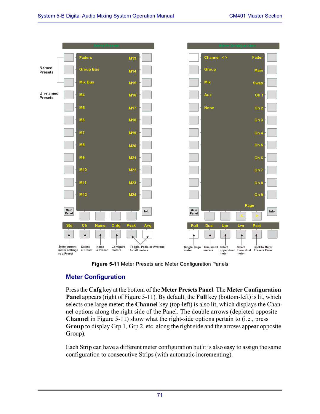
Figure 5-11 Meter Presets and Meter Configuration Panels
Meter Configuration
Press the Cnfg key at the bottom of the Meter Presets Panel. The Meter Configuration Panel appears (right of Figure
Each Strip can have a different meter configuration but it is also easy to assign the same configuration to consecutive Strips (with automatic incrementing).
71