System | Channels and Strips |
|
|
|
|
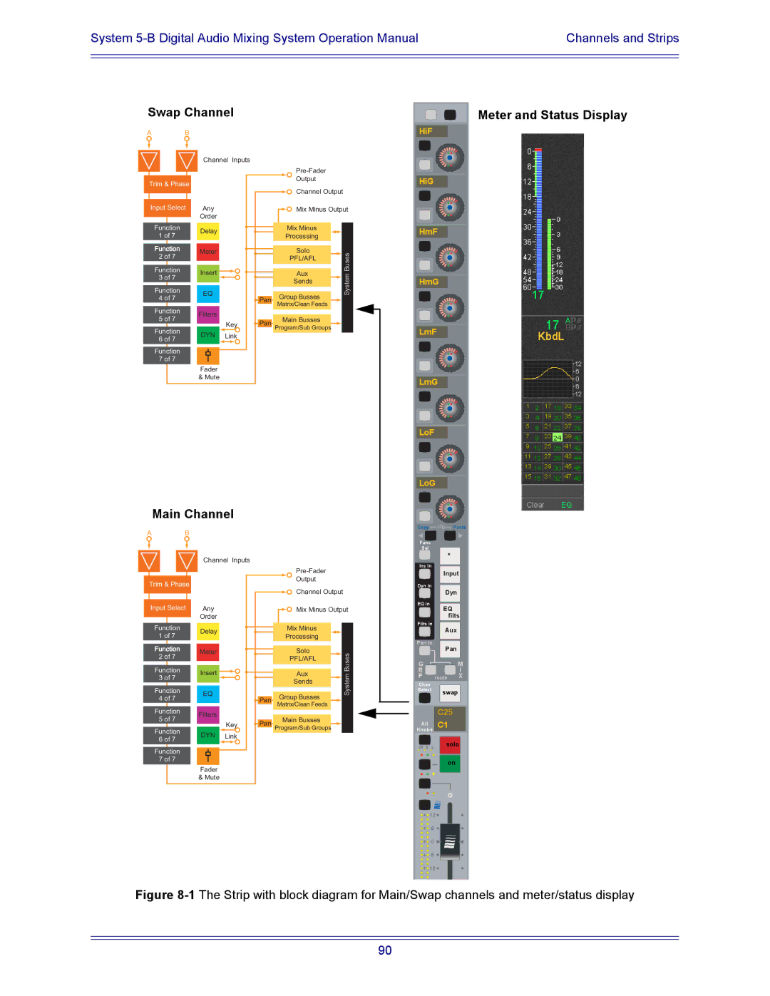
Swap Channel
Meter and Status Display
A B
Trim & Phase
Input Select
Function 21 of 87
Channel | Inputs | |
| ||
| Output | |
| Channel Output | |
Any | Mix Minus Output | |
Order |
| |
Delay | Mix Minus | |
Processing | ||
|
HiF
HiG
HmF
Function
2 of 7
Function 3 of 7
Function 4 of 7
Function 5 of 7
Function 6 of 7
Function 7 of 7
Meter
Insert ![]()
EQ
Filters
Key
DYN Link
Fader
& Mute
|
|
|
| Solo |
|
| Buses |
|
|
|
| PFL/AFL |
|
| |
|
|
|
|
|
|
| |
|
|
|
|
|
|
| |
|
|
|
| Aux |
|
| mte |
|
|
|
|
| |||
|
|
|
| Sends |
|
| |
|
|
|
|
|
|
| Sys |
|
|
|
| Group Busses |
|
| |
|
| Pan |
|
|
|
| |
|
|
| Matrix/Clean Feeds |
|
|
| |
|
|
|
|
|
|
| |
|
|
|
|
|
|
| |
|
|
|
| Main Busses |
|
|
|
|
| Pan |
|
|
|
| |
|
|
| Program/Sub Groups |
|
|
| |
|
|
|
|
|
|
| |
|
|
|
|
|
|
|
|
HmG
LmF
LmG
LoF
LoG
Main Channel
Copy ![]() cfg
cfg![]() Paste
Paste
A B
Trim & Phase
Channel Inputs |
Output |
Func
Sel
*
Ins in
Input
Dyn in
Input Select
| Channel Output |
Any | Mix Minus Output |
Order |
|
EQ in
Dyn
EQ filts
Function 21 of 87
Delay |
|
|
| Mix Minus |
|
|
| ||
|
|
| Processing | |
|
|
|
|
Filts in
Aux
Pan to:
Function
2 of 7
Function 3 of 7
Function 4 of 7
Function 5 of 7
Function 6 of 7
Function 7 of 7
Meter
Insert ![]()
EQ
Filters
Key
DYN Link
Fader
& Mute
|
|
|
| Solo |
|
| Buses |
|
|
|
| PFL/AFL |
|
| |
|
|
|
|
|
|
| |
|
|
|
| Aux |
|
| mte |
|
|
|
|
| |||
|
|
|
| Sends |
|
| |
|
|
|
|
|
|
| Sys |
|
|
|
| Group Busses |
|
| |
|
| Pan |
|
|
|
| |
|
|
| Matrix/Clean Feeds |
|
|
| |
|
|
|
|
|
|
| |
|
|
|
|
|
|
| |
|
|
|
| Main Busses |
|
|
|
|
| Pan |
|
|
|
| |
|
|
| Program/Sub Groups |
|
|
| |
|
|
|
|
|
|
| |
|
|
|
|
|
|
|
|
Pan
G M
RI P route X
Chan
Select swap
C25
All C1
Knobs
M S L | solo |
|
on
![]()
![]()
![]() 12
12![]()
![]()
![]()
![]() 6
6 ![]()
![]()
![]()
![]() 0
0 ![]()
![]()
![]()
![]() 6
6 ![]()
![]()
![]()
![]() 12
12 ![]()
Figure 8-1 The Strip with block diagram for Main/Swap channels and meter/status display
90