701/702
Users Manual
Using Resistance-Temperature Detectors (RTDs)
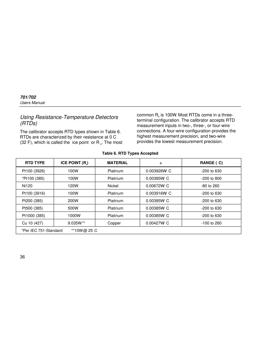
The calibrator accepts RTD types shown in Table 6. RTDs are characterized by their resistance at 0°C (32°F), which is called the “ice point” or R 0. The most
common R0 is 100Ω. Most RTDs come in a three- terminal configuration. The calibrator accepts RTD measurement inputs in
|
|
|
|
|
| Table 6. RTD Types Accepted | |
|
|
|
|
|
|
| |
RTD TYPE | ICE POINT (R0) |
|
|
| MATERIAL | α | |
Pt100 (3926) |
| 100Ω |
| Platinum | 0.003926Ω/°C | ||
*Pt100 (385) |
| 100Ω |
| Platinum | 0.00385Ω/°C | ||
Ni120 |
| 120Ω |
| Nickel | 0.00672Ω/°C | ||
Pt100 (3916) |
| 100Ω |
| Platinum | 0.003916Ω/°C | ||
Pt200 (385) |
| 200Ω |
| Platinum | 0.00385Ω/°C | ||
Pt500 (385) |
| 500Ω |
| Platinum | 0.00385Ω/°C | ||
Pt1000 (385) |
| 1000Ω |
| Platinum | 0.00385Ω/°C | ||
Cu 10 (427) |
| 9.035Ω ** |
|
| Copper | 0.00427Ω/°C | |
*Per IEC | **10Ω @ 25°C |
|
| ||||
|
|
|
|
|
|
|
|
RANGE (°C)
36