701/702
Users Manual
Testing Continuity
In the continuity function, the beeper sounds and the word Short appears on the display when the resistance between the Ω MEAS jack and its common jack is less than 10Ω. The word Open appears when the resistance is greater than 400Ω. Proceed as follows to test continuity:
1.Remove power from the circuit to be tested.
2.If necessary, press Mfor MEASURE mode.
3.Press qtwice so that Open appears.
4.Connect the calibrator to the circuit to be tested as Figure 9 shows.
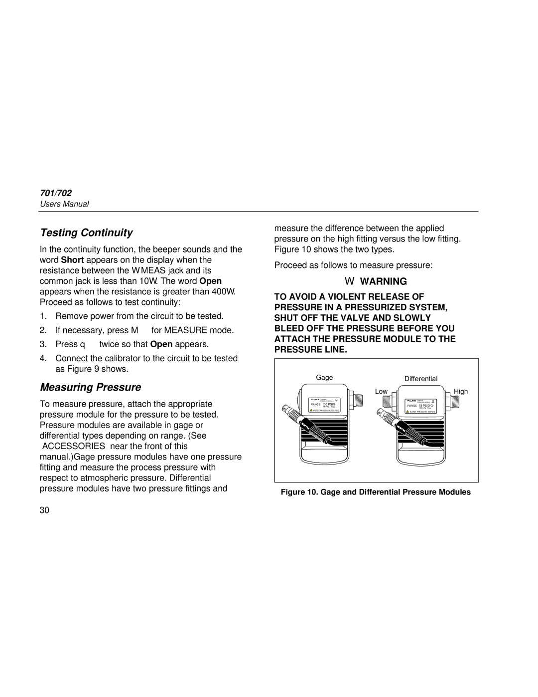
measure the difference between the applied pressure on the high fitting versus the low fitting. Figure 10 shows the two types.
Proceed as follows to measure pressure:
WWARNING
TO AVOID A VIOLENT RELEASE OF PRESSURE IN A PRESSURIZED SYSTEM, SHUT OFF THE VALVE AND SLOWLY BLEED OFF THE PRESSURE BEFORE YOU ATTACH THE PRESSURE MODULE TO THE PRESSURE LINE.
Measuring Pressure
To measure pressure, attach the appropriate pressure module for the pressure to be tested. Pressure modules are available in gage or differential types depending on range. (See “ACCESSORIES” near the front of this manual.)Gage pressure modules have one pressure fitting and measure the process pressure with respect to atmospheric pressure. Differential pressure modules have two pressure fittings and
Gage
![]()
![]()
![]() 700P06
700P06
PRESSURE MODULE
RANGE 100 PSIG
700 kPa 7 bar
![]() BURST PRESSURE 300 PSIG
BURST PRESSURE 300 PSIG
Low
Differential
700P04
PRESSURE MODULE
RANGE 15 PSID/G
100 kPa 1 bar
BURST PRESSURE 45 PSIG
High
Figure 10. Gage and Differential Pressure Modules
30