DH Instruments, a Fluke Company
Operation and Maintenance Manual
RPM4
Page
Table of Contents
Range Unit Mode
2RES Resolution 3STAB 4UL Upper Limit
9RESET
Autorange Leak CK Display
115
MAINTENANCE, Adjustments and Calibration
Remote Operation
Pressure
136
Tables
137
Figures
About this Manual
Manual Conventions
RPM4 Operation and Maintenance Manual
Introduction
Product Overview
Specifications
General Specifications
Pressure Measurement Specifications
Quartz Reference Pressure Transducer Q-RPT
SI Version
RPT
Designation
US Version
Compensated Temperature Range 5 to 35 C
ON-BOARD Barometer
Predicted One Year Stability ± 0.005% of reading
RPTs UP to A10M 1500 psi
Battery and Charger Pack
RPM4 Operation and Maintenance Manual
Installation
Inspecting Contents
Unpacking and Inspection
Removing from Packaging
Setup
Site Requirements
Preparing for Operation
Front and Rear Panels
Power Connection
3.1 85 to 264 VAC, 50/60 HZ VAC Power
Battery Pack
Rear Panel
Remote ENT Connection Footswitch or Other Switch
Connecting to Measure Pressure TEST+ and TEST- Ports
Vent or ATM Port
CHECK/SET Security Level
POWER-UP and Verification
Turn OFF Absolute and Negative Gauge Mode Axxx RPT
Parallel Measurement Mode
Switch Power on
Check Pressure Measurement Operation
Checking Absolute Mode Pressure Measurement
Checking Gauge Mode Pressure Measurement
Short Term Storage
Main RUN Screen
Operation
User Interface
Display Field Name Purpose Contents Section
PRESSURE1UNITM hzRR DDISPLAYFUNCIONnn/nn
Function / Data Keypad Layout and Protocol
Remote ENT Enter Footswitch
General Operating Principles
Sounds
Pressure READY/NOT Ready
Multipe Ranges Q-RPTS, Autorange and Infinite Ranging
RPT Position
Display Symbol
Active A700K DF Hi psi 100g/100a
Using RPM4 with a PPC3 CONTROLLER/CALIBRATOR
Setting Purpose Specific to Section
SDS
Open and close SDS
Measurement mode
AutoRange range
Display
Range
USE of the 12VDC BATTERY/CHARGER Pack
To Charge the Battery
To Use the Battery/Charger Pack to Supply RPM4
To Check the Battery Charge Level
SDS Self Defense System
Direct Function Keys
Direct Function Keys Summary
Range
Summary of RPM4 Function Key Operation
Unit
Operation
Absolute
Mode
1kPa 2Pa 3MPa 4hPa 5bar 6mbar
Measurement mode 1abs 2gage 3neg gage
Gauge
Negative Gauge
Differential
Differential Measurement Mode Operation
Meas mode 1abs 2gage 3neg gage 4dif
Default Display function
Main run screen measured pressure display
SDS function
AutoZ function
SETTING/SELECTION Purpose SET to Section
Absolute mode Zero absolute
Negative gauge mode Minus
Gauge mode Q-RPT with
AutoRange A700K Hi kPa 300g/100a
Set leak check time 15 s
KPa a Leak testing 13 s
Leak CK
Display
∆P 0.61 kPa a Hi Rate 0.06 kPa/sec
1avg 2rate 3dev 4RPT 5HiLo 6freeze 7clean
AVG Average
Averaging Period
20 s
0007 18Avg
Rate
Psi a Hi
0001/sec
Current rate of change of pressure in current
Psi a zH3 D -0.8865 T100.0000
Dev Deviation
Target 100.0000 psi a
6.4 RPT
Psi a zHi Psi g zLo
6.5 Hi/Lo
Psi a zHi H 99.2254 L98.0098
Psi a zHi F
Clean
Freeze
Psi a zHi
Conventional main run screen first line Clean second line
Head
Edit head height
Principle
Pmax! 350 kPa a Hi Open SDS? 1no 2yes
Position designator of Q-RPT for which SDS will be opened
Pmax! 350 kPa a HL Open Hi&Lo? 1no 2yes
AU T O Z
SDS in Differential and Parallel Measurement Modes
Autoz in Gauge and Negative Gauge Mode
Autoz in Absolute Mode
AutoZ Hi abs by 1Entry 2COM2 3Lo RPT
Run AutoZ by Entry
KPa a Pstd,00.00000
Old Poffset 0.0 Pa New Poffset 8.3 Pa
Run AutoZ by COM2
KPa a Pstd,097.7786
Old Poffset 0.0 Pa New Poffset 3.1 Pa
Run AutoZ by Lo RPT
Autoz in Differential Mode
ENT RUN Autotest
1range 2res 3stab 4UL 5ATest
1RANGE
Saving AN Autorange Range
2 2RES Resolution
Deleting Autorange Ranges
Save range A700K Hi kPa 300g/100a
A700K Hi kPa 300g/100a
3 3STAB
Display resltn Hi 0.0010 %FS
4 4UL Upper Limit
Stability Hi 0.020 Pa
Upper limit Hi 204.000 kPa a
Upper Lower-110.00 KPa g
1AutoZ 2remote 3head 4SDS 5prefs 6Punit 7intern 8cal 9reset
Special
5 5ATEST
Over Pressure Function
1 1AU T O Z
AutoZ Purpose and Principle
AutoZ in absolute measurement mode with an Axxx Q-RPT
AutoZ in gauge measurement mode with a Gxxx or BGxxx Q-RPT
AutoZ in differential measurement mode
AutoZ ON/OFF
Recommendations for the Use of the AutoZ Function
1off 2view 3edit Abs on
Active Q-RPT designator
Poffset, Abs
2 2REMOTE
Edit Autoz
2.3 4FORMAT
2.1 1COM1, 2COM2
2.2 3IEEE-488
If a test fails
3 3HEAD
2.4 5RS232 SELF-TEST
SDS temporary Hi 1close 2open
4 4SDS
4.1 1TEMP OPEN/CLOSE
5 5PREFS
4.2 2FULL Time ON/OFF
SDS full time Hi 1on 2off
1ScrSvr 2sound 3time 4ID 5level
5.1 1SCRSVR
5.2 2SOUND
5.3 3TIME
Press SPECIAL, 5prefs, 3time. The display is
5.4 4ID
5.5 5LEVEL Security
Security Levels
Unit Mode
Setup
Function LOW Medium High Range
Leak CK Display Head SDS
Password pppppp Disables password
RPM4 SNnnnn-xx Password pppppp
6 6PUNIT
Selecting 1change user level brings up the restriction menu
Set up unit #6 Unit#6 1SI 2other 3altitude 4user
Define user unit 1.000000 unit/Pa
1SI
2OTHER 3ALTITUDE 4USER
1baro 2ReadRt 3RPT2x 4lo vnt 5log
7 7INTERNAL
7.1 1BARO
Pressure Display Rate of Change Update
7.2 2READRT
Auto read rate 1on 2off
% of range span/s
7.3 3RPT2X
7.4 4LO VNT
Test- vent1auto 2open 3close 4view
Operation See Sections 5.2
8 8CAL
7.5 5LOG
1sets 2units 3ATest 4cal 5all
9 9RESET
9.1 1SETS
Reset Result See Section Unit
9.2 2 Units
9.3 3ATEST
9.4 4 CAL
Reset Result See Section
9.5 5 ALL
All Q-RPT Calibration PA to zero, PM to
All SDS full time on 4.2 DH Instruments, a Fluke Company
Remote Operation
Overview
Interfacing
1 RS232 Interface
Programming Formats
IEEE-488
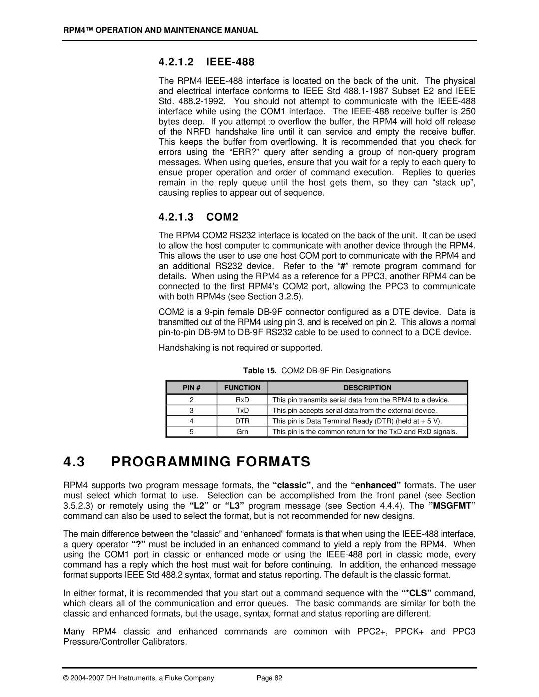
1.3 COM2
PIN # Function Description
Enhanced Program Message Format
Using Command Type Commands
Classic Program Message Format
Using Query Type Commands
Commands
Programming Messages
Error Messagess
Command
VER
Zoffset
Classic
Program Message Description Overview
Enhanced
Program Message Descriptions
#xx
Abort
Enhanced Reply Abort no reply if IEEE-488 Example Sent
ARANGEn
Range
Unit
Mode
AUTOZEROn=RUN
AUTOZEROn
‘state’
Calamb adder, mult CalDate
CALAMB=adder, mult CalDate
Adder
Mult
CONTn
Date
Defaults Head 0, cm, N2 Arguments Height
9999. Setting the value to ‘0’ disables the head correction
Classic GPIB=addr
Classic HEAD=height, units, fluid
L2 / L3
LLn
LLn =limit
Limit
MMODEn
NVENTn
PCALn
Adder, mult CalDate
PCALn= adder, mult CalDate
PRn
PRR
PRR
Qprr
QPRR?
Rng
RATEn
READYCKn
READRATEn
Period
Reset
RESET?
REMOTE?
RESn
RPTn
SDSn
Close
SDSAUTO, Sdsact
SDSAUTOn
Measurement is finished
Lower limits
An internal device failure has occurred
SS%n
SSn
Ready/Not Ready criteria
Hhmm
UCOEFn
ULn
UNITn
UNITn unit , ref UNITn unitn , ref UNITn unitg , ref
UNITn unita , ref UNITn unitd , ref
UNITn=unit , ref
Error Queue
Oper RQS/MSS ESB MAV Error RSR
Status Reporting System
Status Byte Register
RQS/MSS ESB MAV Error RSR
←←← Output Queue ←←← Error Queue
Oper
PON URQ
Standard Event Register
Ready Status Register
PON URQ CMD EXE DDE QYE RQC OPC
Meas Nrdy RDY
Ieee STD .2 Common and Status Program Messages
Program Message Descriptions
RSE
Bit 6 64 is reserved and cannot be set Remarks
Example Sent ∗RST? Enhanced Reply
RPM4 Operation and Maintenance Manual
Principle
Maintenance Adjustments and Calibration
Calibration of Quartz Reference Pressure Transducers Q-RPTS
Corrected reading = uncorrected reading PM + PA
PA and PM Coefficients
AS Received and AS Left Data
OIL or GAS Operated Q-RPTS A14M and Higher
Equipment Required
GAS Operated Q-RPTS, A10M and Lower
SET-UP and Preparation
Recommended Calibration Point Sequence
Standard Class Q-RPTS
Calibration Point Segment
Point Span
Premium Class Q-RPTS
Verification of Premium Class Q-RPTs
SPAN1
25 % 50 % 75 % 100 %
Calibration Point Sequence, Premium Class BGxxx Q-RPTs
15 % 30 % 40 % 45 % 50 % 55 % 60 % 70 % 85 % 100 %
Allow abs Neg g mode? 1yes 2no
RPT Calibration Using Caltool for Rpts Software
Editing and Viewing Q-RPT Calibration Information
000000
Absolute Neg g mode 1on 2off
Cal date20030325 Hi AbsPoffset 0.0 Pa
RPT CALIBRATION/ADJUSTMENT Without Caltool for Rpts Software
As left reading = non-corrected reading new PM + new PA
Adjustment of ON-BOARD Barometer
Non-corrected reading = corrected reading PA/PM + Poffset
Reloading Embedded Software Into Flash Memory
Subassembly Description and Location
Power Supply Module
Mini Micro Board
Micro Card
Driver Board
ON-BOARD Barometer
RPT Module
Display
RPT Module Pneumatic Schematics
Valve
Condition State
Valve Condition State
Axxx Q-RPT A10M with G15K or BGxxx
Troubleshooting
Symptom Probable Cause Solution
Access Restricted
Fatal Fault
Ready green Ready/Not Ready
Check RPT connection
Displayed in second line
SDS Closed is displayed
RPM4 Operation and Maintenance Manual
Remote ENT
Black wire White wire DH Instruments, a Fluke Company
Appendix
Unit Conversion
Pressure
To Convert from Pa To
Multiply by
Warranty
RPM4 Operation and Maintenance Manual
HL Q-RPT
Glossary
DUT
PPC3
Qdut