Track Digital Recorder
Introduction
8288 466
Safety Instructions
Contents
Storing and editing the locate points to the memory keys
Using the Multiple Undo function
Executing of record
Storing and editing Locate key
Loading the data using a adat or S/P DIF digital signal
Multitrack system by the slave mode
External Midi equipment sync system by the slave mode
Saving the deta using Scsi
133
131
132
143
Main features
About copyrights
Precautions
About damage
Front panel-2
Hard disk power LED Green
Detachable remote controller connector
Hard disk access LED Red
Blank panel for installing an optional unit
Auto Play/Auto Return key Auto RTN/PLAY
Controller Connection Cable
Record track select key
Track shift key Track SHIFT/ALL Input
Auto Return Start key
Clipboard In key Clipboard IN/PREVIEW
Clipboard Out key Clipboard OUT/PREVIEW
Auto Punch In key Auto Punch IN/PREVIEW
Display Select key Disp SEL/TIME Base SEL
Auto Return End key Auto RTN END/PREVIEW
Program select key PGM SEL
Store key STORE/HOLD
Next key NEXT/NEXT TC
Recall key Recall
Vari-pitch key Vari PITCH/P. Edit
Previous key PREV/PREV TC
Play button Play
Setup key SETUP/TC GEN
Locate key Locate
Rewind button Rewind
Edit key EDIT/TC Ready
Auto Punch Mode On/Off key Auto Punch
Record button Record
Locate ABS
All Input LED ALL Input
Hard disk access LED green
Foot switch jack Foot SW
Track shift LED 9-16, 17-24 green
Analog Output jack connector Phone
Analog Input jack connector Phone
Remote Thru connector
Remote Input connector
Display section
Preset Display
Switching the display using the Disp SEL key
Changing Programs using the PGM key
Action to take
Display of void
Invalid In/Out indication
Overtime indication
Hard disk E-IDE connection error
Load error indication
Disk error indication
No disk error display
Before Starting
Time Base
Recording method
Recording method and Remain indicator
Remain indicator
Display example
Program You can set up to 99 programs independent containers
Managing songs by Program Change function
Track
Real tracks and Additional tracks
Track
Input monitoring
Input monitoring and playback monitoring
Playback monitoring
About an audio file
What is an event?
Audio file and event
Audio File Recorded part Silence
Hints
Recorded Area File Audio File Event Number
Formatting a current drive disk
Detailed formatting parameters
Available recording time after formatting
Turn on the power to the recorder
Formatting a brand new hard disk Current drive
Press the EXECUTE/YES key
Formatting a backup disk Scsi disk or optional DVD-RAM disk
Press the EXECUTE/YES key while IDE1 or IDE2 isflashing
Optimizing the disk
Exit Setup mode
Press the EXIT/NO key or Stop button to exit Setup mode
Press the EXIT/NO key or the Stop button to
Press the PGM key
Creating a new Program
Turn the JOG dial clockwise
Press the EXIT/NO key, or Stop button
Duplicating a Program
Press the EXIT/NO key or Stop button
Deleting a Program
Using a Program Change function
When the recorder is stopped, press the PGM key
P01 P02 P03 P04 P05 P06 P07
After you enter the title, press the EXECUTE/YES key
Editing a Program title
Press the EXIT/NO key, or the Stop button
Preparation
What is Punch In/Out recording?
Auto Punch In/Out
Storing the edit points
Press the Auto Punch key
Set the track for Auto Punch In/Out to Ready
Auto Punch In/Out Take
Press the Record button while holding down the Play button
Cancelling Rehearsal mode
Manual Punch In/Out
Single Undo/Redo
Manual Punch In/Out take
Hint
Connecting external digital equipment
Digital recording from an external digital device
Selecting a recording Program
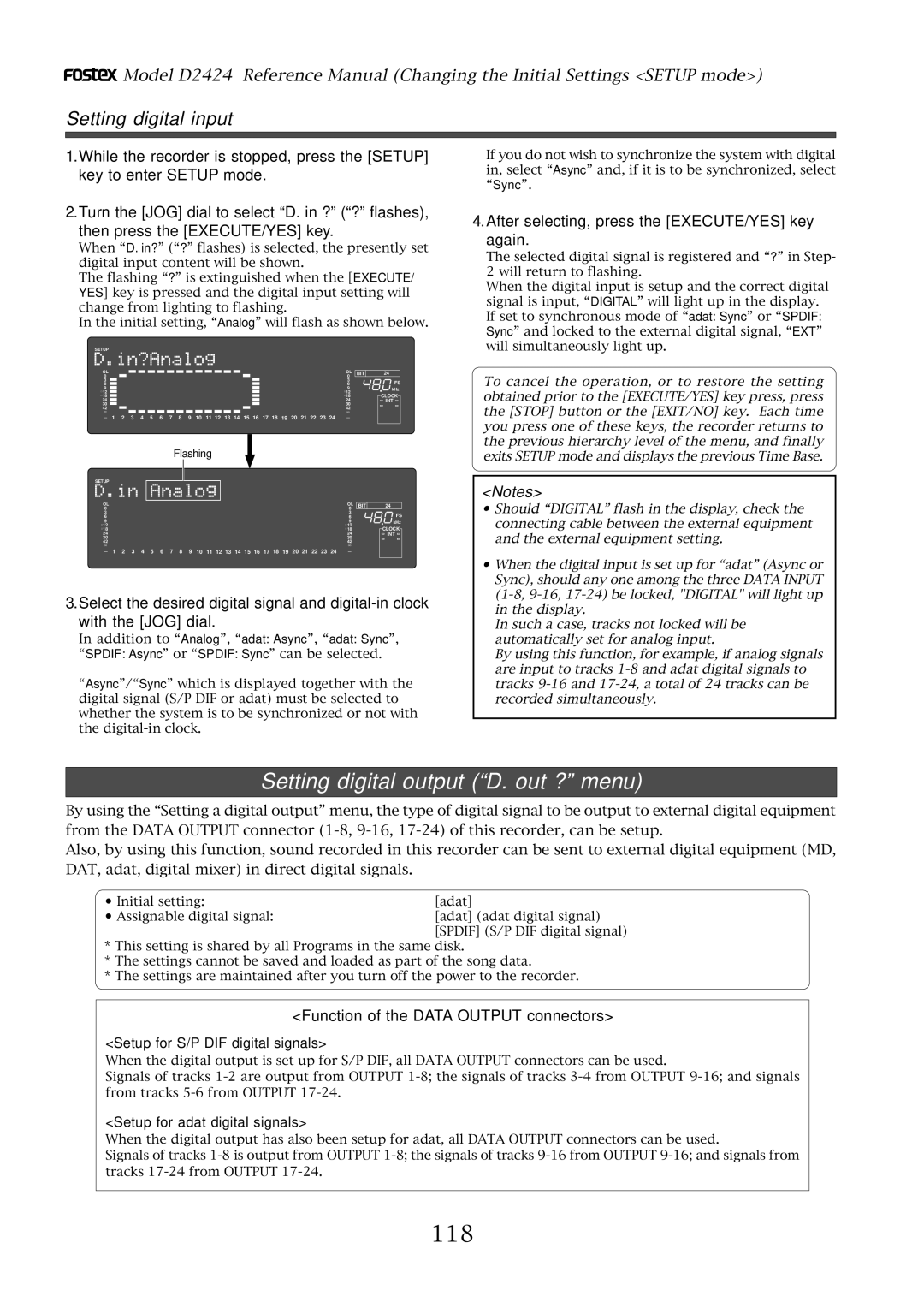
Setting the digital input
Setting recording tracks
Recording
Digital recording to external digital equipment
Int Auto Word Video
Precaution against the digital loop
Connecting a Digital Mixer
Setting the digital output
Digital Mixer
Recording to a Metronome Sound
Turning the Metronome function on
Adjusting monitor/record level of the musical instrument
Creating a Tempo Map
Checking the metronome sound
Clipboard in key
Auto Punch in key
Auto Punch OUT key
Clipboard OUT key
Editing and storing data
Storing and editing the locate points to the memory keys
Storing in real-time
Press the desired memory key
Press the Store key
Storing and editing Locate key
Press the memory key that you pressed in again
Next press the Locate key
Select the Locate number desired using the JOG dial
Edit and re-store data that is already stored
Press the Recall key while the recorder is stopped
Press the Locate key again
Direct Locate
Locate the last-located point Directly press the Locate key
Press the Locate key, or memory key
Auto Play function
Auto Return function
Start playback a little before the Auto RTN END point
Auto Repeat function
Operation of the Auto Repeat mode
Hint
Auto Play mode
Pause mode
Repeat mode
Setup of the Chain Play List
Setup example of the chain play list
Setup of the Chain Play Mode
Specify the Program and Execute Chain Play
Cue & Review function using the Shuttle dial
Cue & Review function using the Rewind and F FWD buttons
Digital scrubbing using the envelope function
Playback point time
Press the Stop button to stop the envelope function
Playback point Track indication
Display indication during the Preview operation
Previewing the rise of the sound fade
Previewing the fall of the sound fade out
Start key, the Auto Punch OUT key, or Clipboard
Memory key Operation
Executing the Preview function
Trimming the sound while previewing
Press the Stop button or the EXIT/NO key
Multiple Undo Function
Keeping multiple takes
Using the Multiple Undo function
Keeping only one take
Press the EXIT/NO key or the Stop button
Copy & Paste
Copy & Paste and Move & Paste
Move & Paste
Executing Copy or Move
Checking and adjusting the edit points
Checking the clipboard data
Executing Paste
Single Undo/Redo Paste
Copy & Paste between programs
Erase
Erasing data from a specified point to REC END
Trim the edit point while previewing
Executing Erase
Single Undo/Redo Erase
Press the Stop button or the EXIT/NO key
Stop mode, press the Edit key to display
Track Exchange
Execution of Track Exchange
TRK Exch.Mono? or TRK Exch.Group?
Flashing
Registering the Track name
Master Recorder
Connecting external equipment Refer to connecting schematic
Midi clock sync system
Midi Sequencer
Setup of the recorder
Confirming the Midi clock sync
Master Recorder
MTC sync/MIDI machine control system
Execution of recording
Midi sound sources
00h Hour 59m Minute 57s Second 00f Frame 00sf Sub Frame
Connecting to external equipment
Setup of external equipment
ABS, Bar Beat
Confirming MTC sync/MMC
00 ~
Setup of the recorder #1 Master
Multitrack system by the slave mode
Equipment interconnections
Vari
Setup of the recorder #2 Slave 1 and #3 Slave
Is set with the Setup mode Midi device ID setting
Vari, Free
Check chase lock
Connection to external equipment
External Midi equipment sync system by the slave mode
Setup of the unit
Master
Set slave type to Vari by the Setup mode Slave type setting
Precautions at MTC related setups
Confirming chase lock
Saving and Loading Song Data
Following items can be saved and loaded as song data
Setting up an external device
Saving the data using a adat or S/P DIF digital signal
Connecting an external device
Executing the save operation
Select the desired track range using the JOG dial
Press the Setup key
Rotate the JOG dial to select a Program to save
Connecting the external device
Loading the data using a adat or S/P DIF digital signal
Executing the load operation
Press the EXECUTE/YES key. SURE? flashes
Play the corresponding external device DAT or adat
Scsi connector Half-pitch 50-pin Scsi cable
Saving the data using Scsi
Connecting a Scsi device
Scsi terminator Removable Scsi drive
Backup format quantization display
Formatting a Scsi disk
Saving data of an individual Program
If you have selected all Programs
When inserting a disk that was used as the current drive
When selecting a Save All ?
When inserting an unformatted disk
Please remember this
Load the data saved on one removable disk
Loading the data using Scsi
Select the backup number and press the EXECUTE/YES key
Press the EXECUTE/YES key while Scsi 6 is flashing
Insert the first disk Disk-1 into the Scsi device
Follow Steps 1-3 of the Loading Song data procedure
Loading data saved on several removable disks
Press the EXECUTE/YES key after selecting the program
Saving and Loading with IDE2 E-IDE Hard disk/DVD-RAM
Press the Setup key when the equipment is stopped
Press the EXECUTE/YES key while FDMS3 is flashing
Loading in the FDMS-3 Mode
Backup Disk
SAVE/LOAD by WAV file
Saving of WAV files
When All Trk is selected
100
After selecting the track, press the EXECUTE/YES key
Title & Eject display
101
After inputting a file name, press the EXECUTE/ YES key
Title & New PGM display
Title & -###MB display
102
Title & ###MB display
Select the WAV file to be loaded with the JOG dial
103
Select the track, then press the EXECUTE/YES key
Method to load specific tracks
Alphabets A-z Numerals Symbols #$%&’@‘=
104
Method in loading by changing the track
Check menu
Changing the initial settings menu
105
Execution menu
Selecting Setup mode
106
Storing a time signature
Time Signature Setting Signature Set?
107
Select a Program for which to set a time signature
Modifying or deleting stored time signatures
Clearing all time signature and tempo settings
108
Changing the bar at ABS 0 of the time base
Select a Program to check the tempo setting for
Setting a tempo Tempo Map Set ? menu
Checking the stored tempo setting
109
110
Modifying or deleting stored tempo settings
Repeat steps 3-5 to store necessary tempo data
111
Setting the Metronome function Click ? menu
Setting the Metronome function
Turn the JOG dial to select On or Off
112
Setting a preroll value Preroll Time ? menu
Setting a preroll time
Turn the JOG dial to enter a desired preroll time value
Setting Midi sync signal
Setting Midi sync output signal Midi Sync Out ? menu
Setting an MTC frame rate Frame Rate ? menu
Turn the JOG dial to select the desired Midi sync signal
Setting an MTC offset
Setting an MTC offset value MTC Offset? menu
Setting an MTC frame rate
114
Use the JOG dial to select the desired Offset mode
Setting Offset mode Offset Mode ? menu
Setting MTC Offset mode
115
Setting the Slave type
Setting the Slave type Slave Type ? menu
Setting the Record Protect function Rec Protect ? menu
116
Use the JOG dial to enable or disable recording
Setting digital input D. in ? menu
Recording enabled/disabled
Function of the Data Input connectors
Function of the Data Output connectors
Setting digital output D. out ? menu
Setting digital input
118
Setting digital output
Setting BAR/BEAT resolution mode Resolution ? menu
119
Use the JOG dial to turn the mode On or Off
Setting the Midi device number Device ID ? menu
Setting the Midi device ID
120
121
Setting the Operating Clock Clock Sel ? menu
Setting the operating clock
Use the JOG dial to set the desired Midi device ID number
122
Checking the number of track events NOs Event ? menu
Checking the number of track events
Setup of the Foot switch function Foot SW? menu
Setup of the Auto EE mode Auto EE Mode? menu
123
Setting the stop function at the mark point
Setting the foot switch function
124
At the -12dB setting At the -20dB setting
Setup of the reference level Ref. Level? menu
Setting the reference level
125
Setting the input/output balance/unbalanced function
Setup of input/output Balance/Unbalance BAL/UNBAL? menu
126
Checking method of the format information
Drive Format Information Drive Info? menu
127
This indicates that the format type was linear
This indicates that it is formatted in FS=48kHz
128
This indicates that the recorder is formatted in 24 bits
This indicates that three programs exist
Setting of the drive
Drive Setting Drive Sel? menu
129
Setting the contrast level
Setup of the display contrast level Contrast ? menu
130
Digital Recorder Model D2424
131
Date Version
132
Fostex Midi System Exclusive Message Format for D2424
133
Status Request
134
135
Allocation of GP0~GP7
136
Data Type
137
Signature map
Explanation on the Command/Mode Set
138
13 42 channelchannel digital out ch.select command
139
14 04 mmc time Preroll time set command
140
141
23 47 midi sync out status request
142
34 08 time base time base status reply
Word Input
Scsi Port for backup
Data Output 1-8, 9-16
Word Output
Memo
Page
Declaration of EC Directive
Musashino, Akishima-shi, Tokyo, Japan
15431, Blackburn Ave., Norwalk, CA 90650, U. S. a