Hardware Description and Installation
An Ethernet hub/switch if you are connecting the device to more than one computer.
For system configuration using the
2.2Physical Appearance
2.2.1Front Panel and LED Indicators
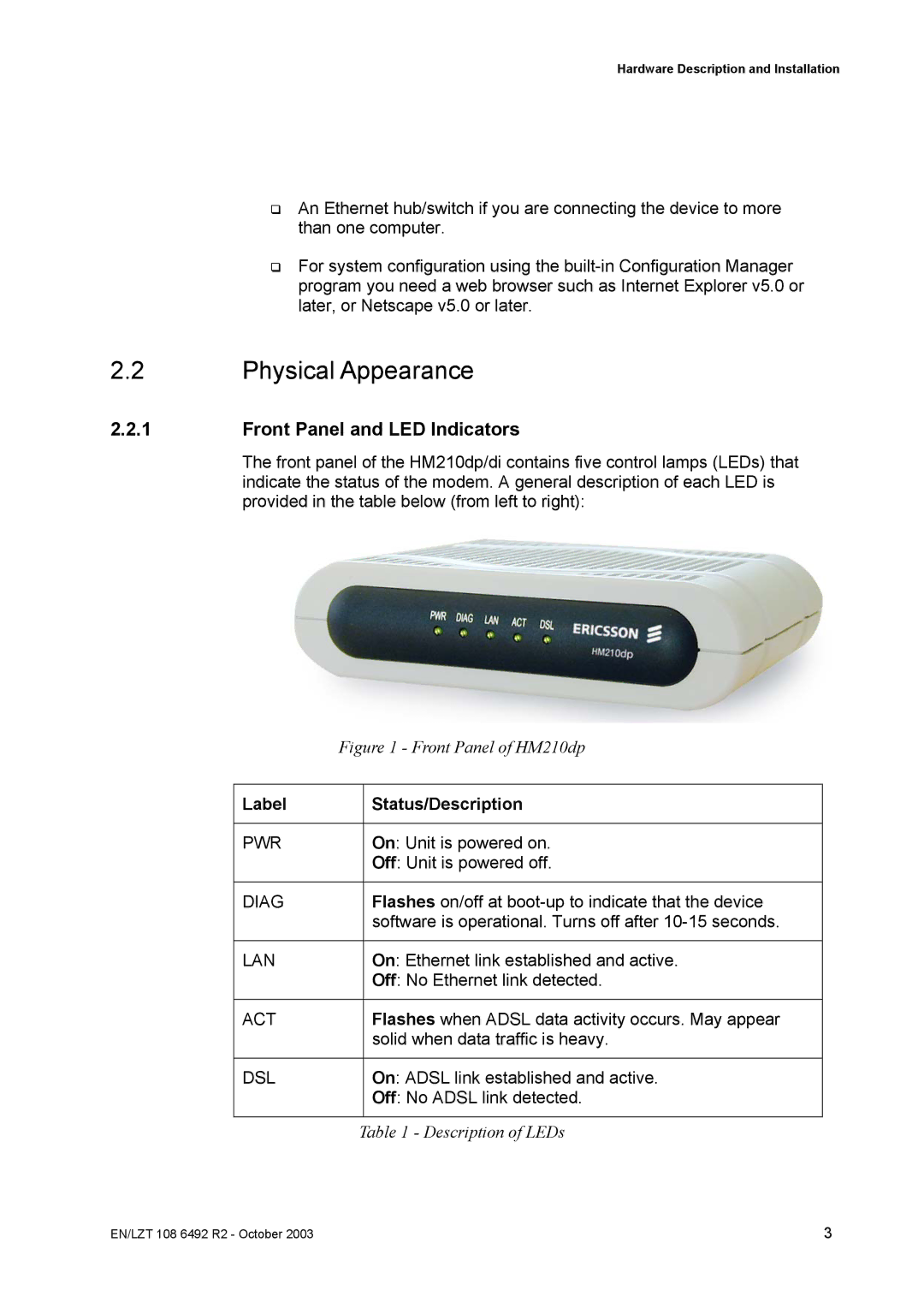
The front panel of the HM210dp/di contains five control lamps (LEDs) that indicate the status of the modem. A general description of each LED is provided in the table below (from left to right):
| Figure 1 - Front Panel of HM210dp | |
|
|
|
Label |
| Status/Description |
|
|
|
PWR |
| On: Unit is powered on. |
|
| Off: Unit is powered off. |
|
|
|
DIAG |
| Flashes on/off at |
|
| software is operational. Turns off after |
|
|
|
LAN |
| On: Ethernet link established and active. |
|
| Off: No Ethernet link detected. |
|
|
|
ACT |
| Flashes when ADSL data activity occurs. May appear |
|
| solid when data traffic is heavy. |
|
|
|
DSL |
| On: ADSL link established and active. |
|
| Off: No ADSL link detected. |
|
|
|
| Table 1 - Description of LEDs | |
EN/LZT 108 6492 R2 - October 2003 | 3 |
