Hardware Description and Installation
2.2.2Back Panel and Connectors
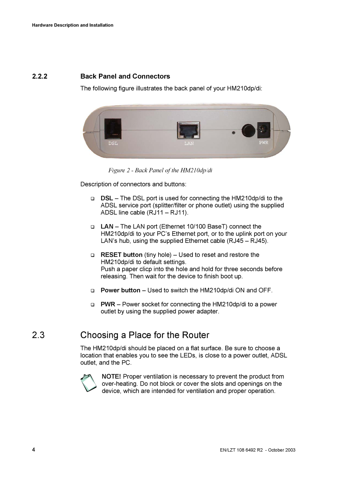
The following figure illustrates the back panel of your HM210dp/di:
Figure 2 - Back Panel of the HM210dp/di
Description of connectors and buttons:
DSL – The DSL port is used for connecting the HM210dp/di to the
ADSL service port (splitter/filter or phone outlet) using the supplied
ADSL line cable (RJ11 – RJ11).
LAN – The LAN port (Ethernet 10/100 BaseT) connect the
HM210dp/di to your PC’s Ethernet port, or to the uplink port on your
LAN’s hub, using the supplied Ethernet cable (RJ45 – RJ45).
RESET button (tiny hole) – Used to reset and restore the HM210dp/di to default settings.
Push a paper clicp into the hole and hold for three seconds before releasing. Then wait for the device to finish boot up.
Power button – Used to switch the HM210dp/di ON and OFF.
PWR – Power socket for connecting the HM210dp/di to a power outlet by using the supplied power adapter.
2.3Choosing a Place for the Router
The HM210dp/di should be placed on a flat surface. Be sure to choose a location that enables you to see the LEDs, is close to a power outlet, ADSL outlet, and the PC.
NOTE! Proper ventilation is necessary to prevent the product from
4 | EN/LZT 108 6492 R2 - October 2003 |