Important Safety Instructions
ProMix PD2K Proportioner for Automatic Spray Applications
Contents
Manual No Description
Related Manuals
Manual No
ECB Labels
Models
0359
Model AC2000 High Pressure Identification Label
Fire and Explosion Hazard
Intrinsic Safety
Personal Protective Equipment
Important Isocyanate ISO Information
Isocyanate Conditions
Keep Components a and B Separate
Moisture Sensitivity of Isocyanates
General Information
Advanced Display Module ADM
USB Download Procedure
ADM Display
USB Upload Procedure
ADM Keys and Indicators
ADM Keys and Indicators Function
Soft Key Functions
Soft Key Icons
Key Function
Key Function
Navigating the Screens
Screen Icons
Power On
Pre-operation Checklist
Pre-Operation Tasks
Flush Before Using Equipment
Initial System Setup
Valve Settings
Without Color Change
With Color Change
Operation Using Automatic Display Module ADM
Prime and Fill the System
Spraying
Purging
Flush Mixed Material
Shutdown
Flush the System
Single Color System
Color Change System
Operation Using a Programmable Logic Controller PLC
Network Communications and Discrete I/O
Discrete I/O
PD2K Discrete I/O Connections
Digital Inputs
Analog Inputs
Discrete I/O Connections on Efcm
KEY
CGM Overview
Communication Gateway Module CGM Details
CGM Kits
Output Register 00 Current System Mode
Number Operation Mode Description
Network Communication I/O Data Map
ProMix PD2K Network Outputs
Output Registers 01, 02, 03, and 04 Pump Status
Pump States for Output Registers Description Ber
Output Register 05 Actual Mix Flow
Output Register 06 Actual Mix Ratio
Output Register 14 Active Recipe Potlife Timeout Set Point
Output Register 27 Safety Interlock Input Status
Output Registers 28 36 DCS Command Structure
Output Register 12 Active Recipe Material B Flush Sequence
Output Register 37 Time
Output Register 38 40 Software Version
Operation Using a Programmable Logic Controller PLC
Network Output Data Map Read Only
None
PSI
= Busy
= ACK
= NAK
= ERR
Input Register 00 System Mode Command
ProMix PD2K Network Inputs
Input Register 03 Mix Pump 1 Control Set Point
Input Register 02 Flush/Prime Pump Command
Input Register 07 Go to Recipe Number
Input Register 08 Clear Active Alarm
Input Registers 14 21 DCS Command Structure
Input Register 09 Job Complete
Input Register 10 Gun 1 Trigger
Operation Using a Programmable Logic Controller PLC
Network Input Data Map Write/Read
40180 Gun 3 Trigger Uint32
Operation Flow Charts
Purge Mode Sequence
Flush Pump Command
Inactive Pump Flush and Prime Sequences
Color Change Sequence
Change
Mixing Sequence
Standby Mix Ready? no
Alarm Clearing Sequence
Clear Active Alarm
Network Communication Dynamic Command Structure DCS
Dynamic Command Description
List of DCS Commands
Dynamic Commands with Command ID
Write User ID
DCS
Write Recipe
Write Flush Sequence
Write Fluid Control Mode
Read User ID
Read Recipe
Read Flush Sequence
Read Fluid Control Mode
Read Job Info
Yymmdd
Yymmdddw
Read Alarm Info
Example Ascii Character String Decode Algorithm
Read Event Info
Flow Control System
Opening Screen
Run Mode Screens
Home Screen
Home Screen Key Description Details
See Advanced Screen 1, page 82, to set
Key Description
Key Description
Spray Screen, in Standby Mode
Spray Screen
Fill Screen
Fill Screen, Color a Selected
Usage Screen
Usage Screen
Jobs Screen
Errors Screen
Events Screen
Setup Mode Screens
Password Screen
System Screen
Mix Idle Timeout
Mix No Flow Timeout
Low Flow Timeout
Mix Pressure Tolerance
Gun Hose Length
Gun Hose Diameter
Mix At Wall
Hose Length and Diameter
Enable
Gateway ID
Gun Trigger Signal
Flow Control Setpoint Signal
Fluid Control
Manual Override
Recipe Screen
Flush Screen
Pump Screen
Default Settings Selected
Default Settings Not Selected
Pressure Alarm and Deviation Limits
Pump Screen 3, Pressure Monitoring Disabled
Calibration Screens
Calibrate Screen
Volume Check Screen
Enter Measured Volume of Solvent
Maintenance Screens
Maintenance Screen
Maintenance Screen 4, Color Valve Resets
Advanced Screen
Enable USB Downloads/Uploads
Log 90% Full Advisory Enabled
Display Units
Download Depth
Pump Pressure Check
Calibration Checks
Perform the pressure check
Pump Volume Check
Solvent Meter Calibration
Scroll to Calibrate Screen 3,
Single Color Systems
Color Change
Multiple Color Systems
To Clear Error and Restart
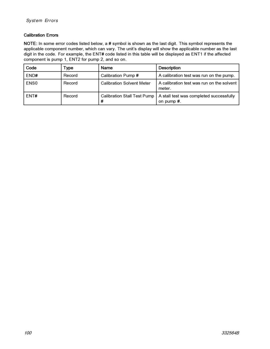
System Errors
Gun Trigger Input Function
Purge Errors Code Type Description Problem Cause Solution
Error Codes
Mix Errors Code Type Description Problem Cause Solution
Pumping Errors Code Type Description Problem Cause Solution
Code Type Description Problem Cause Solution
EBH#
SAD1
Pressure Errors Code Type Description Problem Cause Solution
Qadx
Qbdx
System Errors Code Type Description Problem Cause Solution
Emix
CA0X
CAC#
CDC#
Cagx
Cddx
USB Errors Code Type Description Problem Cause Solution
USB
Wxud
Wxuu
B9BX
B9AX
B9SX
Calibration Errors Code Type Name Description
END#
ENS0
ENT#
Maintenance Errors
Code Type Name Description
Maintenance
Preventive Maintenance Schedule
Cleaning the ADM
Flushing
Technical Data
Positive Displacement Metric Proportioner
Graco Information
Graco Standard Warranty
For Graco Canada Customers