Operation Using Automatic Display Module (ADM)
Flush the System
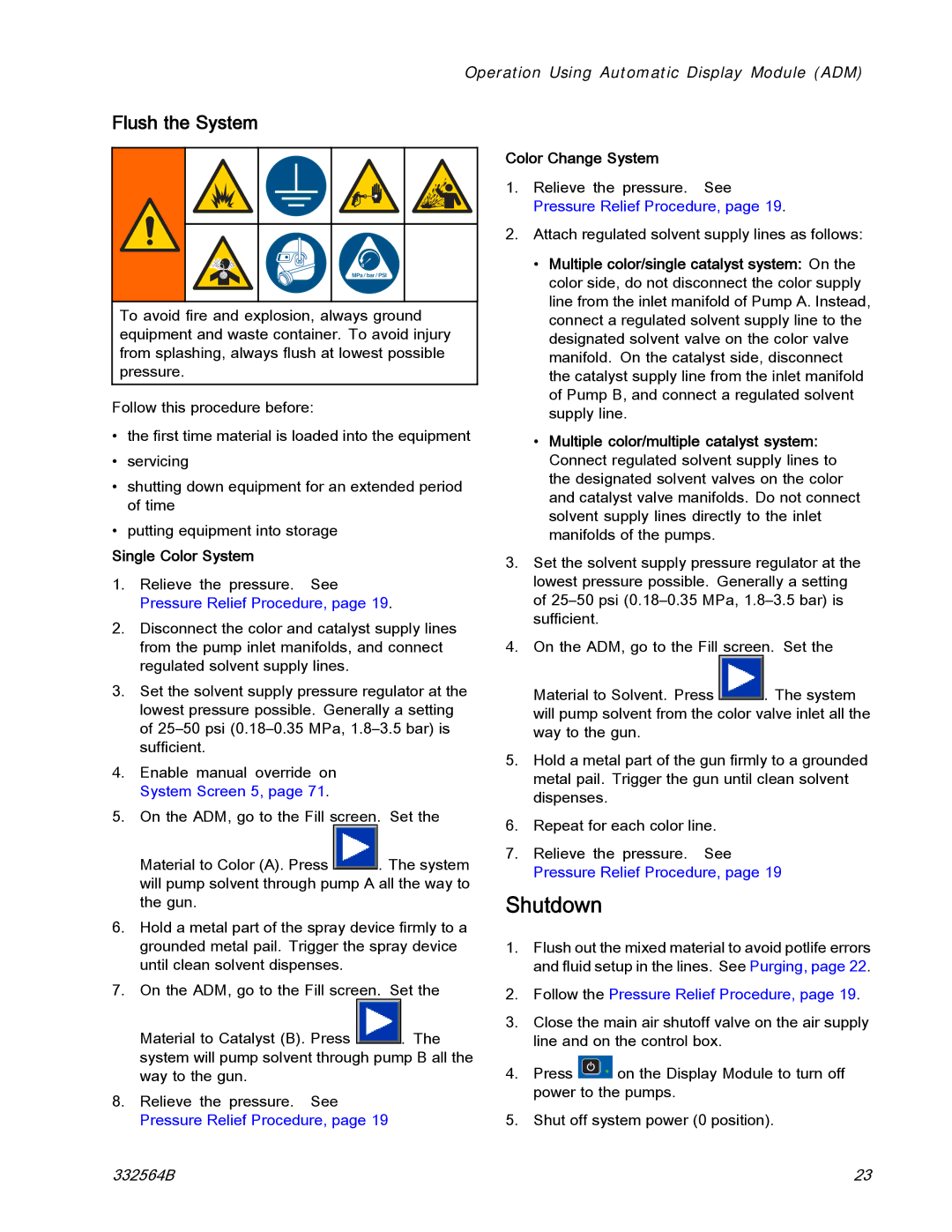
To avoid fire and explosion, always ground equipment and waste container. To avoid injury from splashing, always flush at lowest possible pressure.
Follow this procedure before:
•the first time material is loaded into the equipment
•servicing
•shutting down equipment for an extended period of time
•putting equipment into storage
Single Color System
1.Relieve the pressure. See Pressure Relief Procedure, page 19.
2.Disconnect the color and catalyst supply lines from the pump inlet manifolds, and connect regulated solvent supply lines.
3.Set the solvent supply pressure regulator at the lowest pressure possible. Generally a setting of
4.Enable manual override on System Screen 5, page 71.
5.On the ADM, go to the Fill screen. Set the
Material to Color (A). Press ![]() . The system will pump solvent through pump A all the way to the gun.
. The system will pump solvent through pump A all the way to the gun.
6.Hold a metal part of the spray device firmly to a grounded metal pail. Trigger the spray device until clean solvent dispenses.
7.On the ADM, go to the Fill screen. Set the
Material to Catalyst (B). Press ![]() . The system will pump solvent through pump B all the way to the gun.
. The system will pump solvent through pump B all the way to the gun.
8.Relieve the pressure. See Pressure Relief Procedure, page 19
Color Change System
1.Relieve the pressure. See Pressure Relief Procedure, page 19.
2.Attach regulated solvent supply lines as follows:
•Multiple color/single catalyst system: On the color side, do not disconnect the color supply line from the inlet manifold of Pump A. Instead, connect a regulated solvent supply line to the designated solvent valve on the color valve manifold. On the catalyst side, disconnect the catalyst supply line from the inlet manifold of Pump B, and connect a regulated solvent supply line.
•Multiple color/multiple catalyst system: Connect regulated solvent supply lines to the designated solvent valves on the color and catalyst valve manifolds. Do not connect solvent supply lines directly to the inlet manifolds of the pumps.
3.Set the solvent supply pressure regulator at the lowest pressure possible. Generally a setting of
4.On the ADM, go to the Fill screen. Set the
Material to Solvent. Press ![]() . The system will pump solvent from the color valve inlet all the way to the gun.
. The system will pump solvent from the color valve inlet all the way to the gun.
5.Hold a metal part of the gun firmly to a grounded metal pail. Trigger the gun until clean solvent dispenses.
6.Repeat for each color line.
7.Relieve the pressure. See Pressure Relief Procedure, page 19
Shutdown
1.Flush out the mixed material to avoid potlife errors and fluid setup in the lines. See Purging, page 22.
2.Follow the Pressure Relief Procedure, page 19.
3.Close the main air shutoff valve on the air supply line and on the control box.
4.Press ![]() on the Display Module to turn off power to the pumps.
on the Display Module to turn off power to the pumps.
5.Shut off system power (0 position).
332564B | 23 |