Installation
GND (Ground)
Note All the connectors marked GND are common.
Connect the ground side of the alarm input and/or alarm output to the GND connector.
AO 1 to 16 (Alarm-Out)
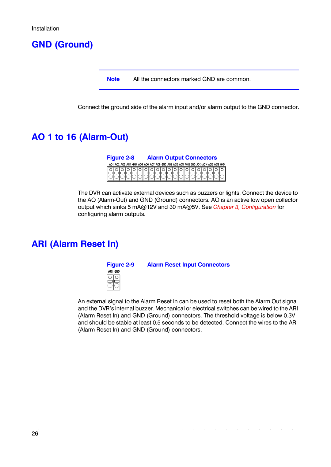
Figure 2-8 Alarm Output Connectors
The DVR can activate external devices such as buzzers or lights. Connect the device to the AO
ARI (Alarm Reset In)
Figure 2-9 Alarm Reset Input Connectors
An external signal to the Alarm Reset In can be used to reset both the Alarm Out signal and the DVR’s internal buzzer. Mechanical or electrical switches can be wired to the ARI (Alarm Reset In) and GND (Ground) connectors. The threshold voltage is below 0.3V and should be stable at least 0.5 seconds to be detected. Connect the wires to the ARI (Alarm Reset In) and GND (Ground) connectors.
26
