Installation
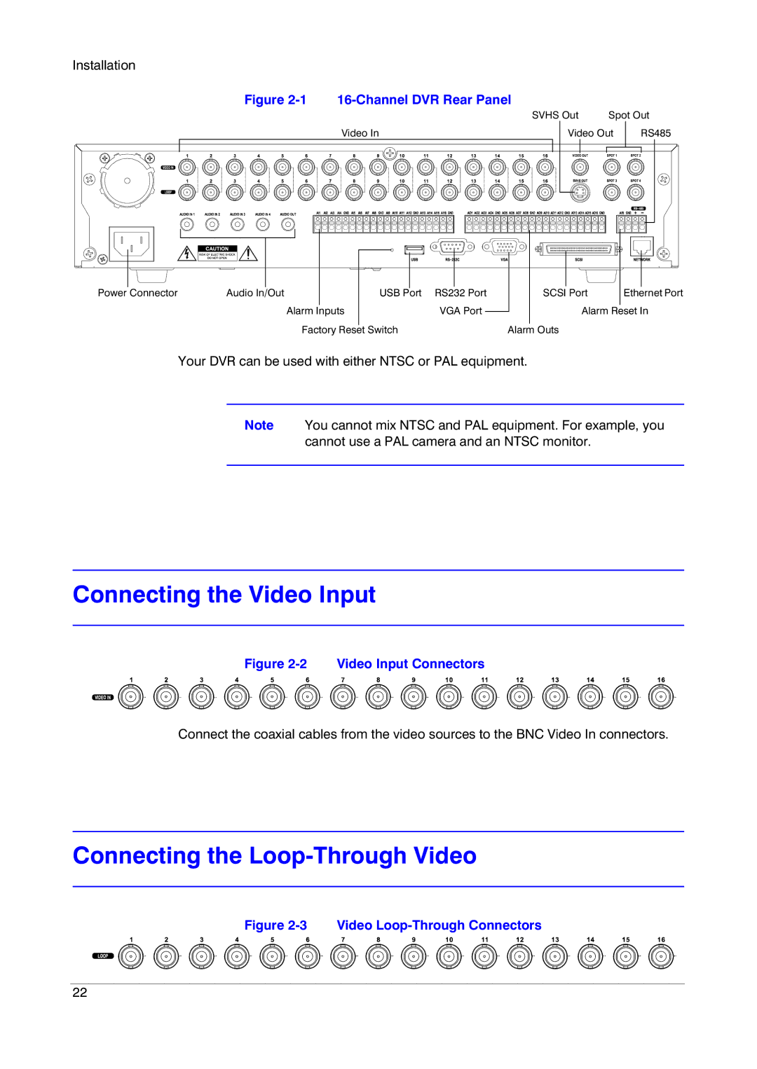
Figure |
|
|
|
|
|
|
|
|
|
|
| SVHS Out | Spot Out | ||||||
| Video In |
|
| Video Out |
| RS485 | |||
|
|
|
|
|
|
|
|
|
|
|
|
|
|
|
|
|
|
|
|
|
|
|
|
|
|
|
|
|
|
Power Connector | Audio In/Out | USB Port | RS232 Port |
|
| Alarm Inputs | VGA Port |
|
| Factory Reset Switch |
|
SCSI Port | Ethernet Port |
Alarm Reset In | |
Alarm Outs
Your DVR can be used with either NTSC or PAL equipment.
Note You cannot mix NTSC and PAL equipment. For example, you cannot use a PAL camera and an NTSC monitor.
Connecting the Video Input
Figure 2-2 Video Input Connectors
Connect the coaxial cables from the video sources to the BNC Video In connectors.
Connecting the Loop-Through Video
Figure 2-3 Video Loop-Through Connectors
22