Configuring HyperFabric
Configuring HMP for Transparent Local Failover Support
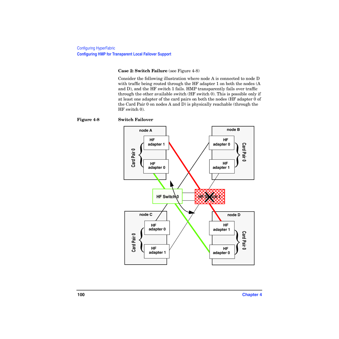
Case 2: Switch Failure (see Figure 4-8)
Consider the following illustration where node A is connected to node D with traffic being routed through the HF adapter 1 on both the nodes (A and D), and the HF switch 1 fails. HMP transparently fails over traffic through the other available switch (HF switch 0). This is possible only if at least one adapter of the card pairs on both the nodes (HF adapter 0 of the Card Pair 0 on nodes A and D) is physically reachable (through the HF switch 0).
Figure | Switch Failover |
| |||
|
|
|
|
|
|
|
|
| node A |
| |
|
|
|
|
|
|
|
|
| { | HF |
|
|
|
| adapter 1 |
| |
|
| CardPair 0 |
|
| |
|
|
|
| ||
|
| HF |
| ||
|
|
|
| adapter 0 |
|
|
|
|
|
|
|
|
|
|
|
|
|
HF Switch 0
node C
| { | HF |
|
| adapter 0 |
| |
CardPair 0 |
|
| |
|
| ||
HF |
| ||
|
| adapter 1 |
|
|
|
|
|
|
|
|
|
node B
| HF |
|
| Card Pair 0 |
| adapter 0 |
| { | |
|
|
| ||
|
|
| ||
| HF |
| ||
|
|
| ||
| adapter 1 |
|
| |
|
|
|
| |
|
|
|
|
|
|
|
|
|
|
HF Switch 1
node D
| HF |
|
|
| adapter 1 |
| Card Pair 0 |
|
| { | |
|
| ||
| HF | ||
|
| ||
| adapter 0 |
| |
|
|
|
|
100 | Chapter 4 |
