Page
Page
PCL 5 Color Technical Reference Manual
Trademarks
Copyright License
What You Can Learn From This Manual
Inside This Manual
Manual Organization
Index
Appendix C. Using Palettes Color LaserJet, 5, 5M, DeskJet
Color Vector Graphics HP-GL/2
Printer Job Language Technical Reference Manual
Related Documents
PCL 5 Printer Language Technical Reference Manual
PCL 5 Comparison Guide
Contents
Modifying Output Color
Raster Graphics
Appendix B Using Color Modes Color LaserJet, 5, 5M, DeskJet
Index
Contents
Introduction
Color Printing Overview
Working with color documents
Color
Color Specifications and Color Spaces
PCL 5 Color Concepts
Page
HP’s ICC profiles are available through normal HP software
PCL 5 Color Graphics Context
PCL 5 Color Mode
Palettes and Color Selection
Pixels and Pixel Encoding
PCL 5 Raster Images
Row Plane Red
Well-Behaved Raster
Color Printing Overview
Simple Color Mode
Black-and-White Mode Default
HP-GL/2 Imaging Mode
PCL Imaging Mode
? *r#U
Simple Color Mode
Simple Color Command
Default Range
Index Color
Single Plane value =
Plane RGB value =
Plane CMY value =
?*v6W b0 b1 b2 b3 b4 b5
PCL Imaging Mode
Configure Image Data CID Command
Byte Value Color Space
Byte 0 Color Space
Value Pixel Encoding Restrictions Mode
Byte 1 Pixel Encoding Mode
PEM 0 Indexed by Plane
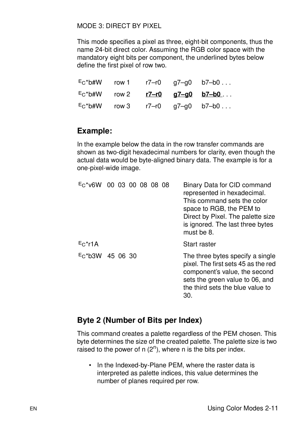
Example
PEM 1 Indexed by Pixel
Mode 2 Direct by Plane
R7-r0 G7-g0
Byte 2 Number of Bits per Index
Bits/Index Indices/Byte
Bytes 3, 4, and 5 No. of Bits for Components 1, 2,
HP-GL/2 Imaging Mode
Using Color Modes
Using Palettes
Page
? *p#P
Push/Pop Palette Command
Saving the Palette
Page
Palette Management by ID
?&p#S
Select Palette Command
Page
?&p#I
Palette Control ID
?&p#C
Palette Control
Page
Simple Color Palettes
Plane CMY value =
Bits/Index = 3 through
CID Color Palettes
Device RGB and sRGB Palettes
Bits/Index =
Bits/Index = 3 through
Device CMY Palettes
Bits/Index = Color
Bits/Index =
Pen Number Color
HP-GL/2 Palettes
Two Pens
Four Pens
Eight Pens
? *v#S
Foreground Color Command
Foreground Color
Color raster images
? *v#A
Programming Color Palettes
Color Component One
Color Component Two
?*v#I
Color Component Three
Assign Color Index
?*v#C
Modifying Output Color
? *t#J
Render Algorithm Command
Halftone Render Algorithms
Device Best Dither
?&b#M
Monochrome Print Mode Command
Monochrome Printing
Select Treatment
Driver Configuration Command
Deviceid
Functionindex
Screen Match
Treatment Command Other Color LaserJet
?&b#F
Finish Mode Command
Default =
PCL Print Model
PCL Print Model
Opaque and Transparency Modes
Page
Effect of Transparency Modes on Images
Operation Comments
Command Sequence
? * v # N
Source Transparency Mode Command
Default
? * v # O
Pattern Transparency Mode Command
Definitions
Logical Operations
Operation
Operators
Operands
Logical Operations and the Print Model
Logical Operations and Transparency Interactions
Roprgb 252 Texture Source Destination
Logical Operation Command
?*l # O
ROPs in the RGB Color Space
ROPs in the CMY Color Space
CMY ROP Truth Tables
Using a ROP
Example
Table of Logical Operations
Logical Operations ROP3 Boolean Input Value Function
Function Input Value
Logical Operations ROP3 Boolean
Logical Operations ROP3 Boolean
Logical Operations ROP3 Boolean
Logical Operations ROP3 Boolean
Pixel Placement
Pixel Placement
Pixel Placement Variations
?*l # R
Pixel Placement Command
HP-GL/2 Patterns
Filling with Patterns
Patterns for Text and Raster Images
Patterns for Rectangles
Selecting User-Defined patterns1
Pattern ID Area Fill ID Command
Shading Patterns
Cross-Hatch Patterns
? * v # T
Select Current Pattern Command
User-Defined Pattern Graphics
Using User-Defined Patterns
How the Printer Tiles a Pattern
10 Pattern Layout Across the Printable Area
Pattern Reference Point
11 Moving Pattern Reference Point for Pattern Filling
Format Byte
Download Pattern Command
Height in Pixels Bytes 4
Continuation Byte
Pixel Encoding Byte
Reserved Byte
User-defined Pattern Example
Page
Previous example, the raster data code is presented
? * p # R
Set Pattern Reference Point Command
? * c # Q
Pattern Control Command
Rectangular Area Fills Rules
? * c # H
Horizontal Rectangle Size PCL Units
Horizontal Rectangle Size Decipoints
? * c # a
? * c #
Vertical Rectangle Size PCL Units
Vertical Rectangle Size Decipoints
? * c # B
? * c # P
Fill Rectangular Area
Printer Language Technical Reference Manual for logical
Pattern Transparency for Rectangular Area Fill
12 Effect of Transparency Modes on Rectangular Areas
Solid Fill Black/White
Rectangular Fill Examples
13 Solid Fill Example
Shaded Fill
Page
PCL Print Model
Raster Graphics
Page
Image Type Number Bits per Components
Raster Area
PCL 5 Color Raster Graphics
Page
Well-Behaved Raster Command Sequence
Raster Graphics Command Sequence
Emphasis in the previous command sequence is that the Raster
? * t # R
Raster Graphics Resolution Command
Raster Graphics Expansion at 300 dpi
? * r # F
Raster Graphics Presentation Mode Command
Default = Range = 0
Raster Graphics Presentation Mode for Portrait Orientation
Raster Graphics Presentation Mode for Landscape Orientation
? * r # T
Source Raster Height Command
Maximum Raster Height
? * r # S
Source Raster Width Command
Maximum Raster Width
? * r # a
Start Raster Graphics Command
Page
? * b # Y
Raster Y Offset Command
Set Compression Method Command
? * b # M
Unencoded Method
Run-length Encoding Method
Tagged Image File Format Encoding Method
# of Bytes Binary value Decimal value 0000 127 0111
Unencoded
Examples Run-length and Tiff Compression
Tiff Encoding
Command byte1 to 8 Replacement bytes
Delta Row Compression Method
Run-length Encoding
Page
Seed Row
11111111
Printing a Zeroed Row Setting the Seed Row to Zero
Repeating a Row
Example Delta Row Compression
Row 00001111 11111111 10101010
Adaptive Compression Method
Value Compression Operation
Duplicate Row
Empty Row
Comparison Guide for specifics
Adaptive Compression Operation Hints
Transfer Raster Data Commands
Transfer Raster Data by Plane
Transfer Raster Data By Row/Block Command
?*b2m3W binary data
Byte Counts and the Tiff v4.0 Compression Mode
? * r C
End Raster Graphics Command
Arbitrary Scaling
Resolution Scaling
Raster Scaling
? * t #
Destination Raster Width
Destination Raster Height
? * t # H
Raster Graphics Example
Page
Page
Example of Raster Graphic Image Data
Color Raster Graphics Example
PCL Command Description Command Arguments
Raster Graphics
Raster Graphics
Color Vector Graphics HP-GL/2
?%#B
Enter HP-GL/2 Mode
Page
Default Settings when Entering HP-GL/2
Page
MC Merge Control
Default
Pixel Combinations Desired Destination Values
Page
Logical Operations ROP3 Boolean Input Value Function
Logical Operations ROP3 Boolean
Logical Operations ROP3 Boolean
Logical Operations ROP3 Boolean
Logical Operations ROP3 Boolean
PC Pen Color
Parameter Format Functional Range Default
Yellow
Shading Fill Type command FT10, the shading levels are
NP Number of Pens
Page
CR Color Range
PP Pixel Placement
Pixel Placement
Parameter Format Functional
PP, Pixel Placement Command
Mode Clamped integer Grid Intersection
Color Printing Overview Color LaserJet, 5, 5M DeskJet
Page
Raster Color vs. Non-Raster Color
Raster Mode
Color Concepts
Palettes
Black and White References
Device-Dependent vs. Device-Independent Color
Scenario White Reference Black Reference
Color Selection
Encoding by Plane
Pixel Encoding
Planar Encoding Pixel Encoding
Color Modes
Encoding by Pixel
C4 c3 c2 c1
Device-Independent Color Spaces
Device-Dependent Color Spaces
Page
Device-Independent Color
Device-Independent Color
Device-Dependent Color
Color Matching
Color Lookup Tables
Color Appearance Matching
Illumination Models
Marking Primitives
Processing Color Documents
Non-Raster Color vs. Raster Color
Color Raster Data
Color Processing Functions
Color Printing Overview Color LaserJet, 5, 5M, DeskJet
Using Color Modes Color LaserJet, 5, 5M DeskJet
Introduction
HP-GL/2 Imaging Mode
Simple Color Mode
Simple Color palettes are shown below
?*v#Wbinary data
Bits/primary #2 Bits/primary #3
Byte 15 MSB LSB Color space Ubyte Pixel encoding mode
Common 6-Byte Header
Bits/index Bits/primary #1
Byte Value Pixel Encoding Mode Restrictions
Mode 0 Indexed by Plane
Mode 1 Indexed by Pixel
Mode 2 Direct by Plane
Bytes are always 1 for this
Byte 3 Number of Bits for Primary #1
Byte 5 Number of Bits for Primary #3
Byte 4 Number of Bits for Primary #2
Short Form of CID Command Configure Image Data
Data Range Scaling
Byte 15 msb Lsb
Long Form of CID Command Configure Image Data
Device RGB Long Form
CIE L*a*b* Long Form
Device CMY Long Form
Byte 15 msb Lsb
Sign Exponent Fractional Portion
Colorimetric RGB Long Form
Byte 15 msb Lsb
Luminance-Chrominance Long Form
Byte 15 msb Lsb
Byte 15 msb Lsb
Device RGB or Device CMY
Examples Using the CID Command
Non-Linear Sony Trinitron
CIE L*a*b
Non-Linear Smpte RGB, 2.2 Gamma, 1.0 Gain
YUV Chrominance-Luminance with Sony Trinitron
YUV Chrominance-Luminance Color Space
HP-GL/2 Imaging Mode
Using Palettes Color LaserJet, 5, 5M DeskJet
Page
Saving the Palette
Page
Palette Management by ID
Select Palette Command
Page
Palette Control ID
Palette Control
Page
Using Palettes Color LaserJet, 5, 5M, DeskJet C-11
Plane CMY value =
Device RGB Palettes
Bits/Index = 3 through
Device CMY and Device-Independent Palettes
HP-GL/2 Palettes
Using Palettes Color LaserJet, 5, 5M, DeskJet C-17
?*v#S
Foreground Color Command
Color raster images
?*v#B
Color Component One
Color Component Two
?*v#A
Assign Color Index
Color Component Three
Using Palettes Color LaserJet, 5, 5M, DeskJet
Modifying Output Color Color LaserJet, 5, 5M DeskJet
Page
?*t#J
Snap Black to White, Colors to Black
Error Diffusion
Snap to Primaries
User-Defined Dithering
Ordered Dither and Clustered Ordered Dither
Monochrome Rendering
Non-Continuous Tone Algorithms
User-Defined Dithers
Download Dither Matrix Command
Byte 15 msb Lsb
Data Bytes
Format
Number of Planes
Height and Width
Multiple Dither Matrices
Example
Byte 15 msb Lsb
Color Lookup Tables
Color Lookup Tables Command
Figure D-1 Color Lookup Tables
Byte 15 msb Lsb
Value Color Space
?*t#I
Gamma Correction Command
Gamma Correction
Viewing Illuminant
Viewing Illuminant Command
Illuminant Chromaticity
Monochrome Print Mode Command
Function Description Argument Range Index
Value Printer Color LaserJet printer
Scaling
Lightness
Saturation
Out of Gamut
No Adjustment
Process Blue
Transparency
Download Color Map
Setting Description MapID Device Dependent
Setting Description MapID
Setting Description MapID Device-Independent
Index
Index-2
Index-3
Index-4
Index-5
Index-6