Color Raster Graphics Example
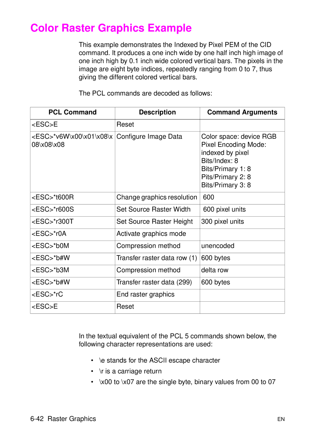
This example demonstrates the Indexed by Pixel PEM of the CID command. It produces a one inch wide by one half inch high image of one inch high by 0.1 inch wide colored vertical bars. The pixels in the image are eight byte indices, repeatedly ranging from 0 to 7, thus giving the different colored vertical bars.
The PCL commands are decoded as follows:
PCL Command | Description | Command Arguments |
|
|
|
<ESC>E | Reset |
|
|
|
|
<ESC>*v6W\x00\x01\x08\x | Configure Image Data | Color space: device RGB |
08\x08\x08 |
| Pixel Encoding Mode: |
|
| indexed by pixel |
|
| Bits/Index: 8 |
|
| Bits/Primary 1: 8 |
|
| Pits/Primary 2: 8 |
|
| Bits/Primary 3: 8 |
|
|
|
<ESC>*t600R | Change graphics resolution | 600 |
|
|
|
<ESC>*r600S | Set Source Raster Width | 600 pixel units |
|
|
|
<ESC>*r300T | Set Source Raster Height | 300 pixel units |
|
|
|
<ESC>*r0A | Activate graphics mode |
|
|
|
|
<ESC>*b0M | Compression method | unencoded |
|
|
|
<ESC>*b#W | Transfer raster data row (1) | 600 bytes |
|
|
|
<ESC>*b3M | Compression method | delta row |
|
|
|
<ESC>*b#W | Transfer raster data (299) | 600 bytes |
|
|
|
<ESC>*rC | End raster graphics |
|
|
|
|
<ESC>E | Reset |
|
|
|
|
In the textual equivalent of the PCL 5 commands shown below, the following character representations are used:
•\e stands for the ASCII escape character
•\r is a carriage return
•\x00 to \x07 are the single byte, binary values from 00 to 07
EN |
