HP LaserJet P3005 Series printers
Page
HP LaserJet P3005 Series printers
Trademark credits
Safety information
Copyright information
Table of contents
Maintenance
Gear assembly
Service approach
Paper feed guide assembly
Reinstallation notes for the gear assembly
Troubleshooting
Order through service or support providers
Print-quality checklist
Wiring diagrams
Paper-handling accessories
Appendix a Specifications
EMI statement Korea
Power cord statement Japan
Vcci statement Japan
Laser statement for Finland
Enww
Alphabetical parts list
Diagnostics menu
Tray 2 pickup assembly
10 Numerical parts list
Xii
Model and serial numbers Systems overview
Print engine general structure
Jam-detection sensors
ECU wiring
Grounding-spring locations
Jetdirect
197
Xvi
Chapter contents
Device information
Device configurations
P3005dn
Features
Feature Description
Accessibility
Supplies
Walkaround
Device parts
Interface ports
Model name Model number
Function
Control-panel layout
Number Button or light
Select
Supported operating systems
Device software
Minimum system requirements
Software for Windows computers
HP Web Jetadmin
Supported printer drivers
HP Easy Printer Care software
Embedded Web server
Software for Macintosh computers
Other software
Remove software from Macintosh operating systems
Uninstall software
Remove software from Windows operating systems
Media specifications
Select print media
1Supported media sizes
Media size Dimensions Weight and thickness
Supported media sizes
2Automatic 2-sided printing
3Tray 1 media types
Type Dimensions
Supported media types
4Tray 2 and tray 3 media types
Paper to avoid
Installation and configuration
Operating environment
Location specifications
Site preparation
Load input trays
Load tray 1 multipurpose tray
Enww
Load tray 2 and optional tray
Enww
Change the print cartridge
Install supplies
Supply replacement guidelines
Enww
Enww
Install device memory
Install accessories
Install memory
Install accessories
Enww
Check Dimm installation
Verify that Dimm is installed correctly
Use HP Jetdirect print server cards
Enable memory for Windows
Install an HP Jetdirect print server card
Remove an HP Jetdirect print server card
Enww
Maintenance
Supplies life
Approximate print-cartridge replacement intervals
Manage supplies
Manage the print cartridge
Print-cartridge authentication
HP fraud hotline and Web site
Clean the paper path
Clean the device
Clean the exterior
Clean spilled toner
Create and use the cleaning
Use information pages
Description How to print
Management tools
File directory
Use the HP Easy Printer Care software
Open the HP Easy Printer Care software
PCL or PS font list
HP Easy Printer Care software sections
SectionOptions
Embedded Web server sections
Open the embedded Web server by using a network connection
Use the embedded Web server
Tab or section Options
Or Sleep mode on
Settings tab
Tab or section
Use HP Web Jetadmin software
Use the HP Printer Utility for Macintosh
Networking tab
HP Printer Utility features
Open the HP Printer Utility
Theory of operation
Basic operation
Formatter
Engine control unit ECU
Formation roller
3Engine control system circuit diagram Theory of operation
ECU
Pickup/feed/delivery system
Laser/scanner system
6Laser/scanner system
Image-formation system
8Image-formation system Theory of operation
Developing
Primary charging
Laser beam exposure
Separation
Fusing
Transfer
Drum cleaning
13 Fusing
Internal components
15Cross-section of device
Internal components
1Operation sequences
2Power-on sequence
Timing
Name Timing Purpose
16Operational sequences
Timing diagram
Print cartridge memory system
Write
Enww
Removal and replacement
Separation pad
Electrostatic discharge
Removal and replacement strategy
Overview
Required tools
Types of screws
Illustration Description Size Part number Use
Pre-service procedures
Service approach
Before performing service
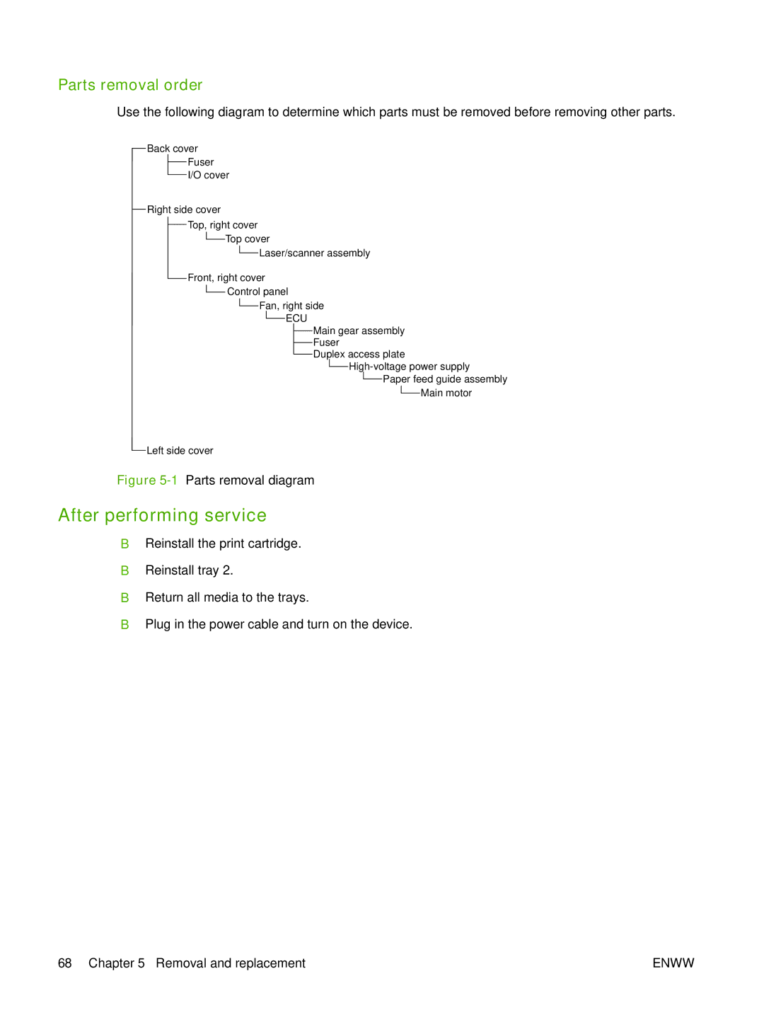
After performing service
Parts removal order
Covers
Right-side cover
Left-side cover
Enww
Back cover
Cover
Top, right cover
6Removing the I/O cover Lift the cover off of the device
Top cover
Front, right cover
8Removing the top cover Lift the cover off of the device
9Removing the front, right cover 1 Removal and replacement
Enww
Control panel
12Reinstalling the control panel
13Removing the formatter 1 Removal and replacement
Formatter
14Removing the formatter 2
15Removing the formatter 3 Removal and replacement
Fuser
Back cover see Back cover on Cover see I/O cover on
17Removing the fuser 2 Removal and replacement
Enww
19Removing the laser/scanner 1 Removal and replacement
Laser/scanner
Laser/scanner
21Removing the ECU 1 Removal and replacement
Engine control unit ECU
22Removing the ECU 2
23Removing the ECU 3 Removal and replacement
24Removing the ECU 4
25Removing the ECU 5 Removal and replacement
26Removing the ECU 6
27Removing the ECU 7 Removal and replacement
Enww
Access plate
High-voltage power supply
31Removing the power supply 1
Enww
33Removing the power supply 3
Enww
35Removing the power supply 5
Enww
37Reinstalling the oblique-roller assembly
Paper feed guide assembly
Paper feed guide assembly
Main motor
40Removing the main motor 2
Gear assembly
41Removing the gear assembly 1 Removal and replacement
Remove four screws callout 3 from the gear-assembly plate
Reinstallation notes for the gear assembly
43Reinstalling the gear assembly Removal and replacement
Tray 1 solenoid
Tray 2 solenoid
Label reader memory tag
46Removing the e-label reader 1
Enww
Face-down-roller shaft
48Removing the face-down-roller shaft 1
Enww
Cartridge door
50Removing the cartridge door 1
51Removing the cartridge door 2 Removal and replacement
52Removing the cartridge door 3
Transfer roller
Registration assembly
54Removing the registration assembly 1
Enww
Remove four screws callout
Tray 1 pickup roller
Tray 2 pickup roller
Enww
Separation pad
Enww
Troubleshooting
Troubleshooting process
Basic troubleshooting
Resolve control-panel messages
Control-panel messages
Control-panel message types
Control panel message Description Recommended action
10.XX.YY Supply Memory Error
XX Internal Clock Error
JAM Inside Rear Door
JAM Inside TOP Cover
JAM Inside Front Door
13.XX.YY Fuser JAM Inside TOP
13.XX.YY JAM in Tray
13.XX.YY JAM Inside Duplexer
Insufficient Memory
13.XX.YY JAM Inside Rear Door
13.XX.YY JAM Inside TOP Cover
TOO Complex
Parallel I/O Buffer Overflow
EIO X Buffer Overflow
Embedded I/O Buffer Overflow
Serial I/O Buffer Overflow
Embedded I/O BAD Transmission
Error
Xxxxx Error
Unexpected Size in Tray
To continue turn off then on
Fuser Error
XY Error
No System
55.XX.YY DC Controller Error
Alternates with Formatter To continue turn off then on
Permanent Storage Full
Storage Error Settings
8X.YYYY EIO Error
Permanent Storage Write Fail
On Tray
8X.YYYY Embedded Jetdirect
Action not Currently Available
Custom Chosen Personality not
Close TOP Cover
Code CRC Error
Install Black Cartridge
Data Received
Load Tray X Type Size
Insufficient Memory to Load
FONTS/DATA
Load Tray 1 Plain Paper
MEM Test Failure Replace Dimm
NON HP Supply Installed
Manually Feed Output Stack
NON HP Supply in USE
RAM Disk File System is Full
RFU Load Error
RAM Disk File Operation Failed
RAM Disk is Write Protected
Tray XX Open
USB Accessory Error
Tray XX Empty Type Size
Tray XX Open or Empty
USB Storage X Removed
USB Storage File System is Full
USB Storage is Write Protected
USE Tray X Type Size
Avoid jams
Cause Solution
Clear jams
1Common causes of jams
Typical jam locations
Jam detection
1Jam-detection sensors
Clear jams from the input-tray areas
Jam type Description
Enww
Clear jams from the print-cartridge area
Clear jams from the output-bin areas
Clear jams from the optional duplexer
Enww
Communications checks
Interface troubleshooting
EIO troubleshooting
Computer direct connect parallel test
Network printing problems
Jetdirect
Packet Size
Nvram initialization
Service mode functions
Cold reset
Skip disk-load
Service menu service PIN codes
Hard-disk initialization
Self test
Service ID
Restoring the service ID
Convert the service ID to an actual date
2Diagnostics menu
Troubleshooting tools
Diagnostics menu
Control-panel menus
Test pages
Engine-test
Formatter test
Image defect ruler
Determine the current firmware version
Upgrade the firmware
Use FTP to upgrade the firmware on a network connection
Use HP Web Jetadmin to upgrade the firmware
Use MS-DOS commands to upgrade the firmware
\YOURSERVER\YOURCOMPUTER
Upgrade the HP Jetdirect firmware
Device does not pull media from a tray Cause Solution
Troubleshoot general printing problems
Device selects media from the wrong tray CauseSolution
Paper curls when it exits the device Cause Solution
Print job prints on both sides of the paper Cause Solution
Pages print, but are totally blank Cause Solution
Messages and see Control-panel messages on
Pages are wrinkled or folded
Troubleshoot media handling problems
Multiple pages feed
Pages are skewed
Assembly on
Troubleshoot print-quality problems
Print-quality checklist
Image-defect examples
AaBbCc
Light print partial
AaBbCc
Light print entire
Specks
Dropouts
Lines
Gray background
Toner smear
Loose toner
Repeating defects
Repeating image
Misformed characters
Skew
Curl or wave
Wrinkles or creases
Vertical white lines
Tire tracks
White spots on black
Scattered lines
Blurred print
Random image repetition
Main assemblies
Diagrams
Device component locations
Main parts
Main parts
Sensors and switches
6Sensors and switches
Motors, fans, and solenoids
7Motors, fans, and solenoids
Wiring diagrams
PCAs
3 4 12 11
10Circuit diagram 1 196 Chapter Troubleshooting
Circuit diagram 2
Enww
Parts and diagrams
Order directly from HP
Order parts, accessories, and supplies
Order through service or support providers
Order directly through the HP Easy Printer Care software
Print cartridge
Paper-handling accessories
Part numbers
Memory
Cables and interfaces
Enww
Covers
Covers
Description Part number Qty
2Internal components 1 Parts and diagrams
2Internal components 1
Enww
Enww
3Internal components 2 Parts and diagrams
3Internal components 2
502 Pin, dowel XD3-2120-122 503 Ring, E XD2-1200-802
Enww
4Internal components 3 Parts and diagrams
4Internal components 3
5Internal components 4 Parts and diagrams
5Internal components 4
6Internal components 5 Parts and diagrams
6Internal components 5
7Internal components 6
7Internal components 6
Tray 2 pickup assembly
8Tray 2 pickup assembly Parts and diagrams
8Tray 2 pickup assembly
Alphabetical parts list
9Alphabetical parts list
Connector, snap tight, bk VS1-7177-004
Film, fuser drive side plate RC2-0649-000
Internal components 4
Holder, switch link RC2-0634-000
Motor, DC M1, main RK2-1488-000
Registration assembly RM1-3715-000
Sensor-flag assembly RM1-3769-000
Spring, torsion RU5-2386-000
Part number Description
Numerical parts list
10Numerical parts list
RC1-4061-000 Spring, torsion
RC2-0468-000 Cushion, right lower
RC2-0612-000 Cover, engine controller
RC2-0705-000 Lever, drive release
RM1-3716-000 Multipurpose paper pick-up roller assembly
RM1-4040-000 Top sensor PCA PS901
RU5-2386-000 Spring, torsion
XA9-1503-000 Screw, tap, M3x6
Enww
Specifications
Device model Height Depth Width Weight
Physical specifications
Table A-1Device dimensions
Device model Height Depth Width
Table A-4Power consumption average, in watts
Electrical specifications
Table A-3Power requirements
Specification Volt models
Operating environment
Acoustic specifications
Table A-5Sound power and pressure level
Table A-6Necessary conditions
Service and support
Hewlett-Packard limited warranty statement
Customer self repair warranty service
Print cartridge limited warranty statement
HP Customer Care
Online Services
HP service agreements
HP Easy Printer Care software
HP support and information for Macintosh computers
Next-day on-site service
HP maintenance agreements
On-site service agreements
Weekly volume on-site service
Extended warranty
Enww
Regulatory information
FCC regulations
Environmental product stewardship program
Material restrictions
HP print supplies returns and recycling program information
Paper
HP LaserJet P3005 device
Material Safety Data Sheet Msds For more information
Enww
Declaration of conformity
Declaration of Conformity
Canadian DOC regulations
Safety statements
Laser safety
Laser statement for Finland
Luokan 1 laserlaite
Enww
Index
ECU
Enww
Msds
RFU
Enww
See also trays
Trays status
Enww
Page
Q7812-90910