RC3000 Antenna Controller | Chapter 3 | Detailed Operation |
3.3 Programming Group
The programming group has two
3.3.1 Configuration Mode
The CONFIG mode allows users to view and/or modify various controller parameters and to enable or disable certain features. Many configuration items are used to customize the RC3000 to work with a particular installation.
The CONFIG mode groups configuration items into screens containing between 1 to 10 individual items. The
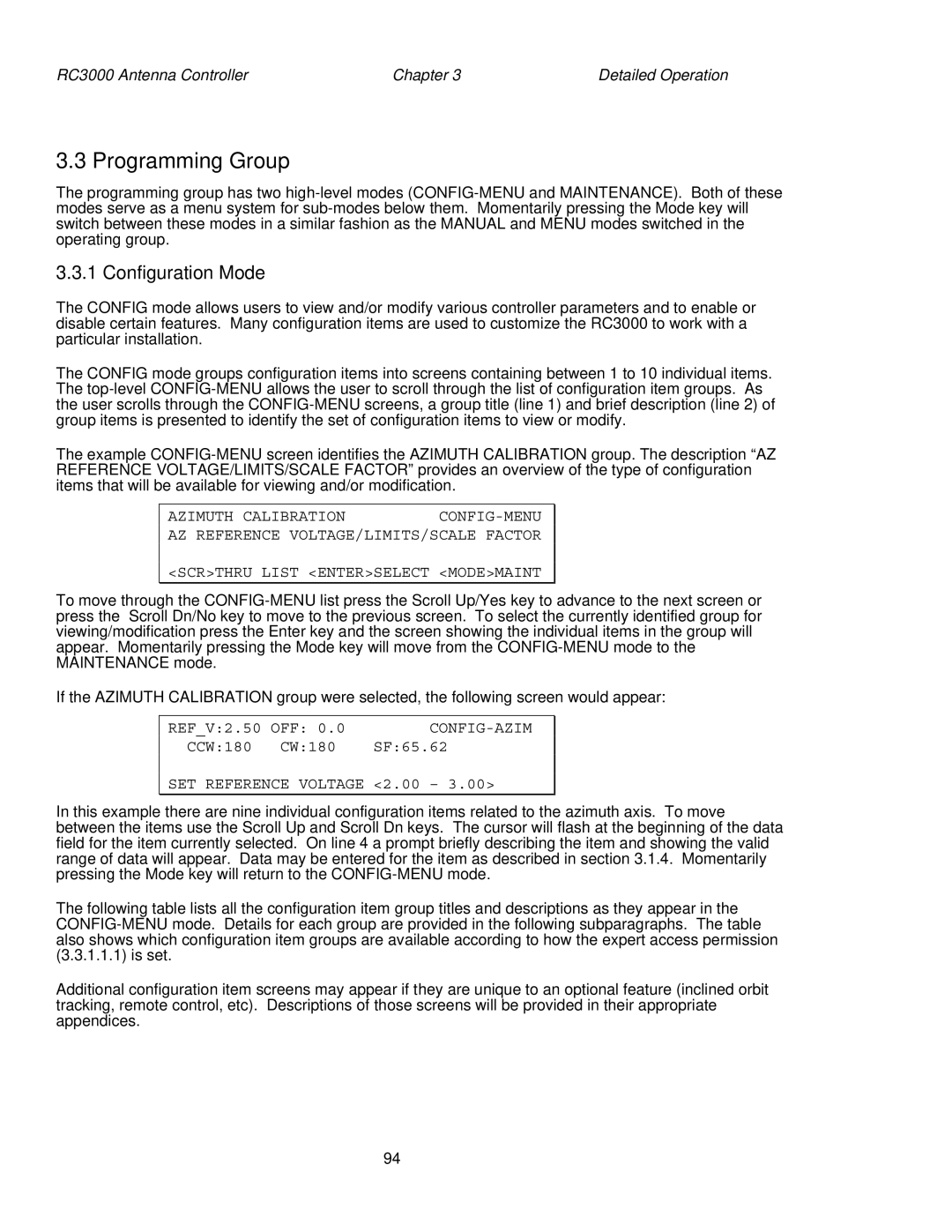
The example
AZIMUTH CALIBRATION
AZ REFERENCE VOLTAGE/LIMITS/SCALE FACTOR
<SCR>THRU LIST <ENTER>SELECT <MODE>MAINT
To move through the
If the AZIMUTH CALIBRATION group were selected, the following screen would appear:
REF_V:2.50 OFF: 0.0 | |
CCW:180 CW:180 | SF:65.62 |
SET REFERENCE VOLTAGE <2.00 – 3.00>
In this example there are nine individual configuration items related to the azimuth axis. To move between the items use the Scroll Up and Scroll Dn keys. The cursor will flash at the beginning of the data field for the item currently selected. On line 4 a prompt briefly describing the item and showing the valid range of data will appear. Data may be entered for the item as described in section 3.1.4. Momentarily pressing the Mode key will return to the
The following table lists all the configuration item group titles and descriptions as they appear in the
Additional configuration item screens may appear if they are unique to an optional feature (inclined orbit tracking, remote control, etc). Descriptions of those screens will be provided in their appropriate appendices.
94
