RC3000 Antenna Controller | Chapter 3 | Detailed Operation |
3.2.2.3.3 Azimuth Scanning Autopeak
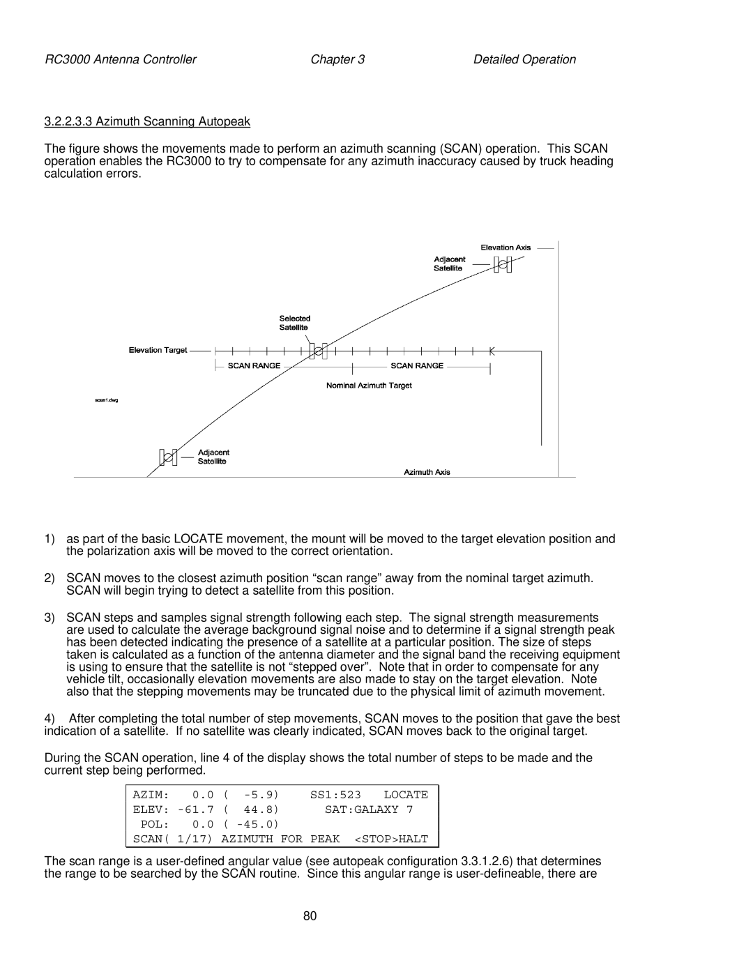
The figure shows the movements made to perform an azimuth scanning (SCAN) operation. This SCAN operation enables the RC3000 to try to compensate for any azimuth inaccuracy caused by truck heading calculation errors.
1)as part of the basic LOCATE movement, the mount will be moved to the target elevation position and the polarization axis will be moved to the correct orientation.
2)SCAN moves to the closest azimuth position “scan range” away from the nominal target azimuth. SCAN will begin trying to detect a satellite from this position.
3)SCAN steps and samples signal strength following each step. The signal strength measurements are used to calculate the average background signal noise and to determine if a signal strength peak has been detected indicating the presence of a satellite at a particular position. The size of steps taken is calculated as a function of the antenna diameter and the signal band the receiving equipment is using to ensure that the satellite is not “stepped over”. Note that in order to compensate for any vehicle tilt, occasionally elevation movements are also made to stay on the target elevation. Note also that the stepping movements may be truncated due to the physical limit of azimuth movement.
4)After completing the total number of step movements, SCAN moves to the position that gave the best indication of a satellite. If no satellite was clearly indicated, SCAN moves back to the original target.
During the SCAN operation, line 4 of the display shows the total number of steps to be made and the current step being performed.
AZIM: | 0.0 | ( | SS1:523 LOCATE | |
ELEV: | ( | 44.8) | SAT:GALAXY 7 | |
POL: | 0.0 | ( |
| |
SCAN( | 1/17) | AZIMUTH FOR PEAK <STOP>HALT | ||
The scan range is a
80