RC3000 Antenna Controller | Chapter 1 | Introduction |
The Fast/Slow Transition parameter defines how far away from a target position the RC3000 will switch from fast to slow motor speed. The Coast Range defines where the RC3000 will
Note that the DC motor control module in the RC3000 provides for smooth acceleration/deceleration, load regulation and dynamic braking of the motors.
1.3.7 Polarization Control
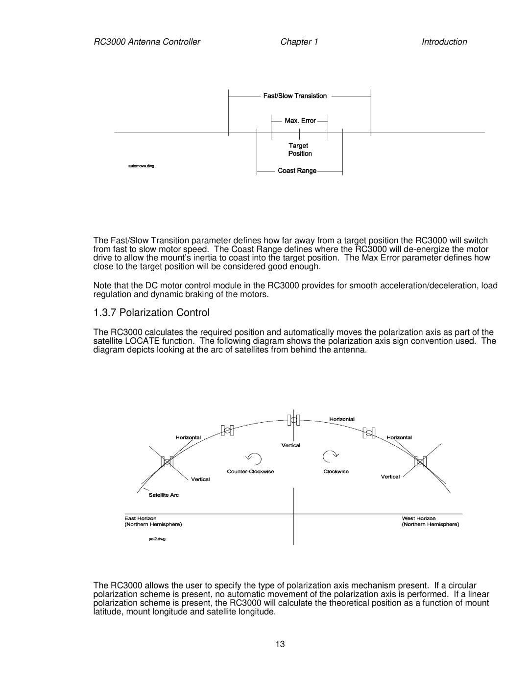
The RC3000 calculates the required position and automatically moves the polarization axis as part of the satellite LOCATE function. The following diagram shows the polarization axis sign convention used. The diagram depicts looking at the arc of satellites from behind the antenna.
The RC3000 allows the user to specify the type of polarization axis mechanism present. If a circular polarization scheme is present, no automatic movement of the polarization axis is performed. If a linear polarization scheme is present, the RC3000 will calculate the theoretical position as a function of mount latitude, mount longitude and satellite longitude.
13