RC3000 Antenna Controller | Chapter 3 | Detailed Operation |
3.2.1.2 Waveguide Switch
For mounts equipped with the optional waveguide switch control module, manual control of the waveguide switch may be initiated via the MANUAL mode.
NOTE: The WAVEGUIDE SWITCH configuration item on the System Definition screen (3.3.1.2.1) must be set in order for software to allow the changing of the waveguide switch position from the Manual mode.
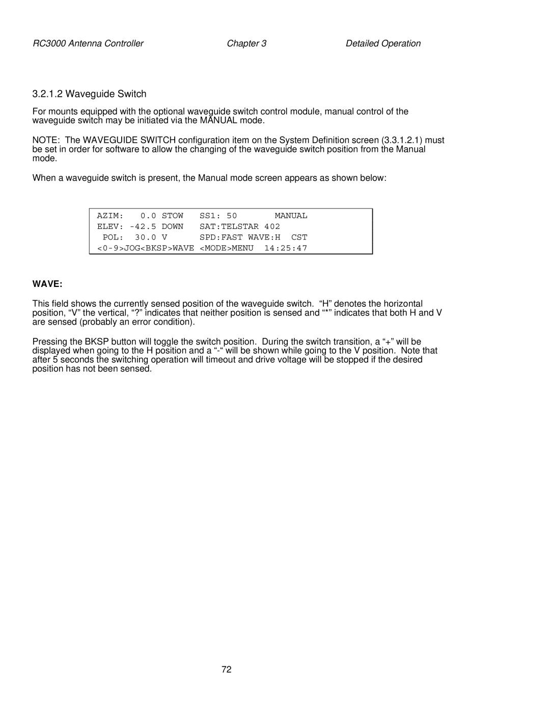
When a waveguide switch is present, the Manual mode screen appears as shown below:
AZIM: | 0.0 | STOW | SS1: 50 | MANUAL | |
ELEV: | DOWN | SAT:TELSTAR | 402 |
| |
POL: | 30.0 | V | SPD:FAST WAVE:H | CST | |
| <MODE>MENU | 14:25:47 | |||
WAVE:
This field shows the currently sensed position of the waveguide switch. “H” denotes the horizontal position, “V” the vertical, “?” indicates that neither position is sensed and “*” indicates that both H and V are sensed (probably an error condition).
Pressing the BKSP button will toggle the switch position. During the switch transition, a “+” will be displayed when going to the H position and a
72