RC3000 Antenna Controller | Chapter 2 | Installation |
2.4.3 Signal Strength Adjustment
The RC3000 can sense satellite signal strength via the
2.4.3.1 L-Band Power Detector
The simplest detection scheme is to connect LNB output to the
See section 3.3.1.2.6 (Autopeak configuration) for a discussion of the characteristics of the
2.4.3.2 Signal Strength Channel
To implement tracking algorithms and the LOCATE mode’s scan/search, the controller requires an input signal which indicates the strength of the received signal. Such a signal is generated within a satellite receiver, and is referred to as an AGC signal. (AGC is the abbreviation for Automatic Gain Control.) On satellite receivers, this signal may also be referred to as a 'Signal Strength' or 'Tuning Meter' output. An AGC output typically varies in proportion to the received power of the transponder which the receiver is currently tuned to.
Signal strength indications from receivers, modems, etc. vary widely. The RC3000 provides two circuits that are designed to accommodate any signal strength input that varies between +/- 15 VDC. The 2 circuits have the same design, but different component values installed optimize channel 1 for use with signal strength inputs that vary by less than 1.3 VDC. Channel 2 circuitry has a lower gain that would be more optimal for use with signal strength inputs that vary by more than 1.3 VDC. A particular installation’s unique set of receiver(s) will dictate which channel(s) are used.
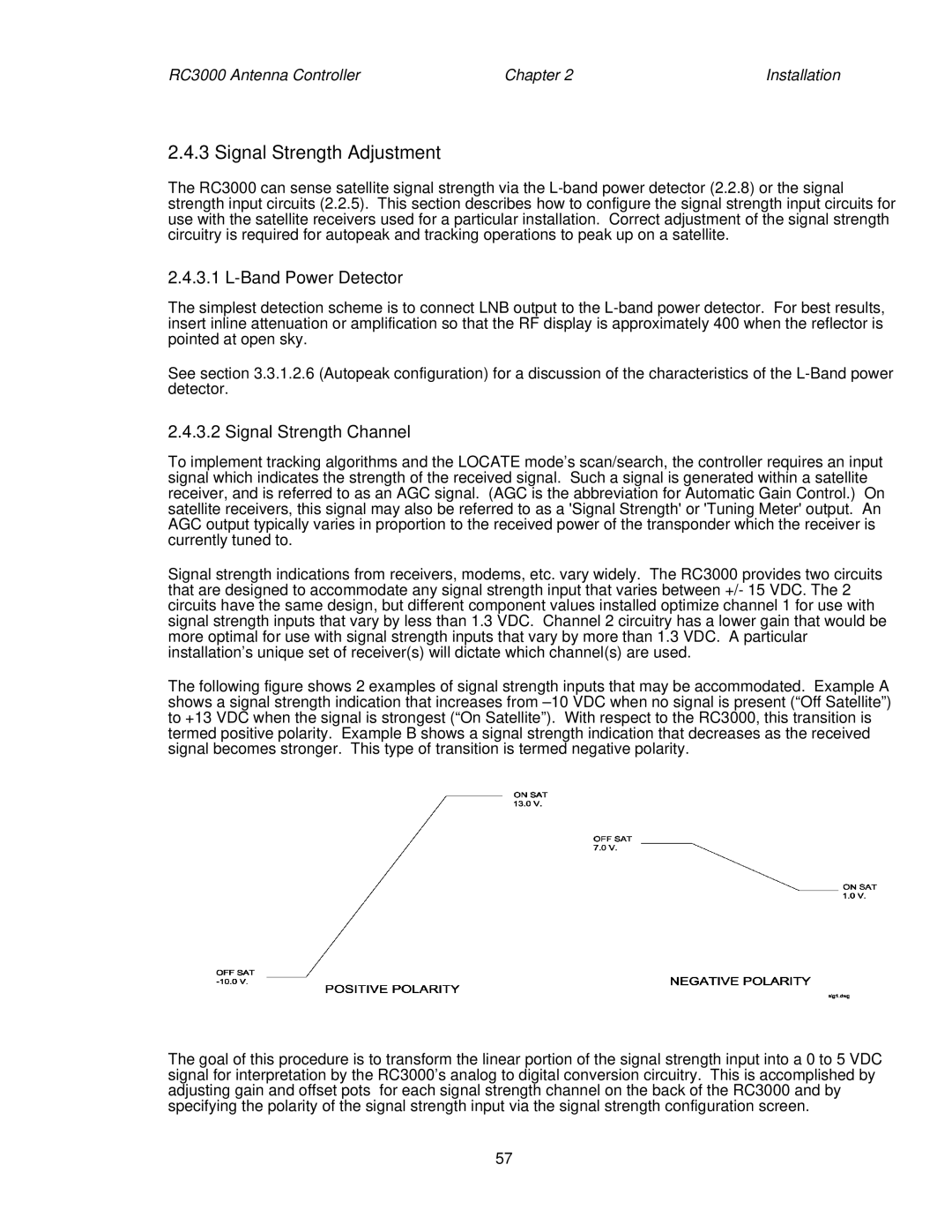
The following figure shows 2 examples of signal strength inputs that may be accommodated. Example A shows a signal strength indication that increases from
The goal of this procedure is to transform the linear portion of the signal strength input into a 0 to 5 VDC signal for interpretation by the RC3000’s analog to digital conversion circuitry. This is accomplished by adjusting gain and offset pots for each signal strength channel on the back of the RC3000 and by specifying the polarity of the signal strength input via the signal strength configuration screen.
57