RC3000 Antenna Controller | Chapter 2 | Installation |
2.1.4 Electronic Clinometer
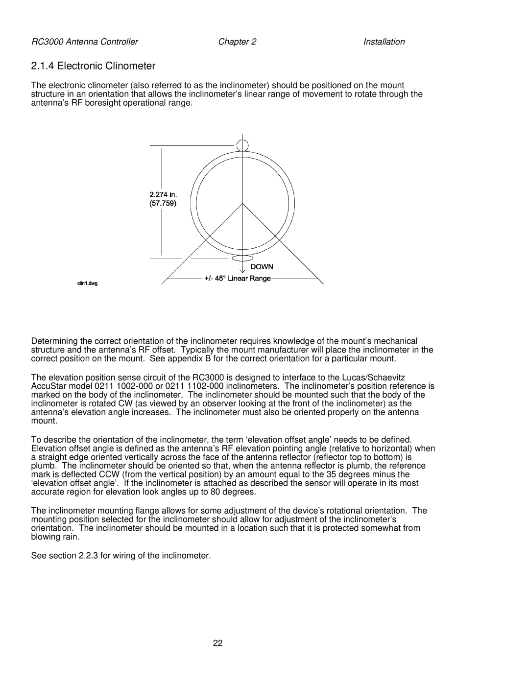
The electronic clinometer (also referred to as the inclinometer) should be positioned on the mount structure in an orientation that allows the inclinometer’s linear range of movement to rotate through the antenna’s RF boresight operational range.
Determining the correct orientation of the inclinometer requires knowledge of the mount’s mechanical structure and the antenna’s RF offset. Typically the mount manufacturer will place the inclinometer in the correct position on the mount. See appendix B for the correct orientation for a particular mount.
The elevation position sense circuit of the RC3000 is designed to interface to the Lucas/Schaevitz AccuStar model 0211
To describe the orientation of the inclinometer, the term ‘elevation offset angle’ needs to be defined. Elevation offset angle is defined as the antenna’s RF elevation pointing angle (relative to horizontal) when a straight edge oriented vertically across the face of the antenna reflector (reflector top to bottom) is plumb. The inclinometer should be oriented so that, when the antenna reflector is plumb, the reference mark is deflected CCW (from the vertical position) by an amount equal to the 35 degrees minus the ‘elevation offset angle’. If the inclinometer is attached as described the sensor will operate in its most accurate region for elevation look angles up to 80 degrees.
The inclinometer mounting flange allows for some adjustment of the device’s rotational orientation. The mounting position selected for the inclinometer should allow for adjustment of the inclinometer’s orientation. The inclinometer should be mounted in a location such that it is protected somewhat from blowing rain.
See section 2.2.3 for wiring of the inclinometer.
22