HP manual RC3000 Antenna Controller Chapter Installation

Models: RC3000

1 143
Download 143 pages 35.5 Kb
Page 44
Image 44

RC3000 Antenna Controller

Chapter 2

Installation

and falling edges must not exceed 65535, 2) the duration of the high and low segments of the waveform must be at least 10 milliseconds, 3) the high level of the waveform must be 4.5 to 5.7 volts, and 4) the low level of the waveform must be 0.0 to 0.5 volts.

A number of manufacturers make sensors which may be placed directly between the motor and the transmission on the C56 flange; Dart's CF Series (ph.
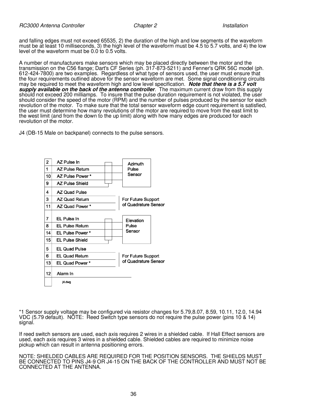
 317-873-5211) and Fenner's QRK 56C model (ph. 612-424-7800) are two examples. Regardless of what type of sensors used, the user must ensure that the four requirements outlined above for the sensor waveform are met. Some signal conditioning circuits may be required to meet the waveform high and low level specification. Note that there is a 5.7 volt supply available on the back of the antenna controller. The maximum current draw from this supply should not exceed 200 milliamps. To insure that the pulse duration requirement is not violated, the user should consider the speed of the motor (RPM) and the number of pulses produced by the sensor for each revolution of the motor. To make sure that the total sensor waveform edge count requirement is satisfied, the user must determine how many revolutions of the motor are required to move from the east limit to the west limit (and from the down to the up limit) along with how many edges are produced for each revolution of the motor.

J4 (DB-15 Male on backpanel) connects to the pulse sensors.

*1 Sensor supply voltage may be configured via resistor changes for 5.79,8.07, 8.59, 10.11, 12.0, 14.94 VDC (5.79 default). NOTE: Reed Switch type sensors do not require the pulse power (pins 10 & 14) signal.

If reed switch sensors are used, each axis requires 2 wires in a shielded cable. If Hall Effect sensors are used, each axis requires 3 wires in a shielded cable. Shielded cables are required to minimize noise pickup which can result in antenna positioning errors.

NOTE: SHIELDED CABLES ARE REQUIRED FOR THE POSITION SENSORS. THE SHIELDS MUST BE CONNECTED TO PINS J4-9 OR J4-15 ON THE BACK OF THE CONTROLLER AND MUST NOT BE CONNECTED AT THE ANTENNA.

36

Page 44
Image 44
HP manual RC3000 Antenna Controller Chapter Installation