RC3000 Antenna Controller | Chapter 2 | Installation |
2.2.12 Waveguide Switch
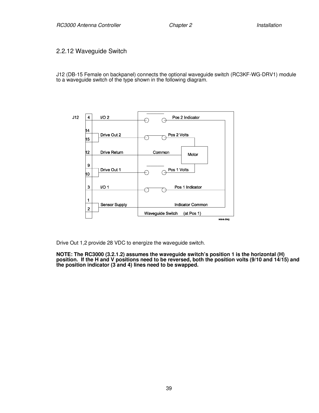
J12
Drive Out 1,2 provide 28 VDC to energize the waveguide switch.
NOTE: The RC3000 (3.2.1.2) assumes the waveguide switch’s position 1 is the horizontal (H) position. If the H and V positions need to be reversed, both the position volts (9/10 and 14/15) and the position indicator (3 and 4) lines need to be swapped.
39
