RC3000 Antenna Controller | Chapter 2 | Installation |
2.3.3 Azimuth Calibration
Steps to perform azimuth calibration will be described starting with the azimuth axis in the stowed position and the elevation axis above the DOWN limit. Movement in the azimuth axis is not allowed until the elevation DOWN limit switch is inactive.
The mount should be moved to the exact azimuth position that it will be stowed. Typically this is near the midway point of its range of movement in azimuth. Also, the azimuth stow limit switch should be in the center of its activation region. It is very important that this position be confirmed in this manner or problems could be encountered during the automatic stow function.
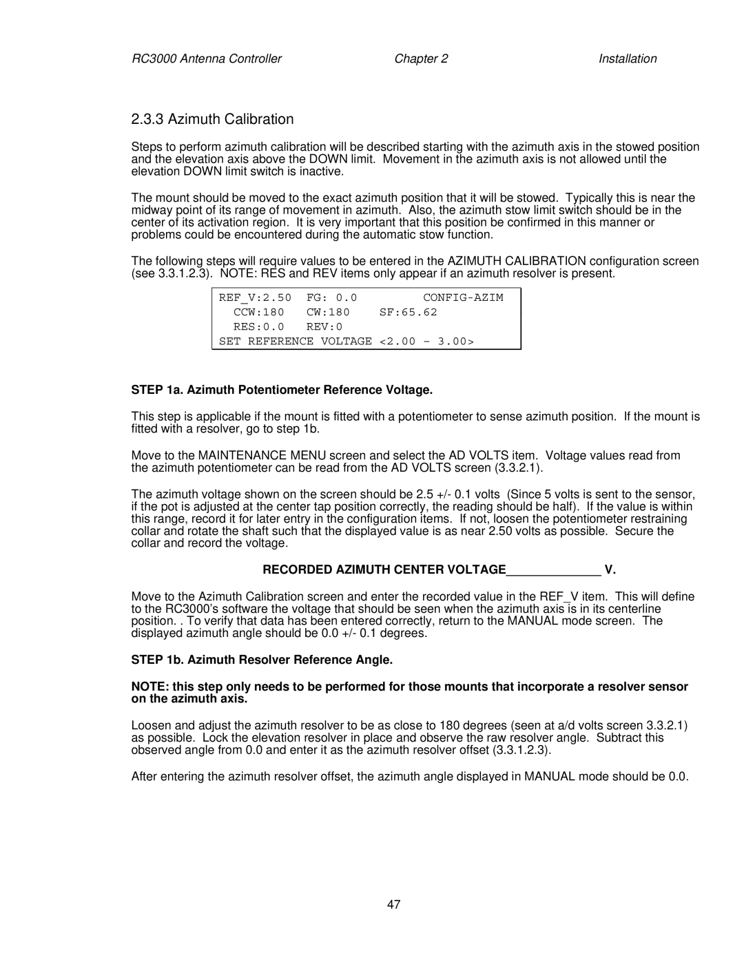
The following steps will require values to be entered in the AZIMUTH CALIBRATION configuration screen (see 3.3.1.2.3). NOTE: RES and REV items only appear if an azimuth resolver is present.
REF_V:2.50 | FG: 0.0 | |
CCW:180 | CW:180 | SF:65.62 |
RES:0.0 | REV:0 |
|
SET REFERENCE VOLTAGE <2.00 – 3.00>
STEP 1a. Azimuth Potentiometer Reference Voltage.
This step is applicable if the mount is fitted with a potentiometer to sense azimuth position. If the mount is fitted with a resolver, go to step 1b.
Move to the MAINTENANCE MENU screen and select the AD VOLTS item. Voltage values read from the azimuth potentiometer can be read from the AD VOLTS screen (3.3.2.1).
The azimuth voltage shown on the screen should be 2.5 +/- 0.1 volts (Since 5 volts is sent to the sensor, if the pot is adjusted at the center tap position correctly, the reading should be half). If the value is within this range, record it for later entry in the configuration items. If not, loosen the potentiometer restraining collar and rotate the shaft such that the displayed value is as near 2.50 volts as possible. Secure the collar and record the voltage.
RECORDED AZIMUTH CENTER VOLTAGE______________ V.
Move to the Azimuth Calibration screen and enter the recorded value in the REF_V item. This will define to the RC3000’s software the voltage that should be seen when the azimuth axis is in its centerline position. . To verify that data has been entered correctly, return to the MANUAL mode screen. The displayed azimuth angle should be 0.0 +/- 0.1 degrees.
STEP 1b. Azimuth Resolver Reference Angle.
NOTE: this step only needs to be performed for those mounts that incorporate a resolver sensor on the azimuth axis.
Loosen and adjust the azimuth resolver to be as close to 180 degrees (seen at a/d volts screen 3.3.2.1) as possible. Lock the elevation resolver in place and observe the raw resolver angle. Subtract this observed angle from 0.0 and enter it as the azimuth resolver offset (3.3.1.2.3).
After entering the azimuth resolver offset, the azimuth angle displayed in MANUAL mode should be 0.0.
47