RC3000 Antenna Controller | Chapter 2 | Installation |
2.2.2 Motor Drive
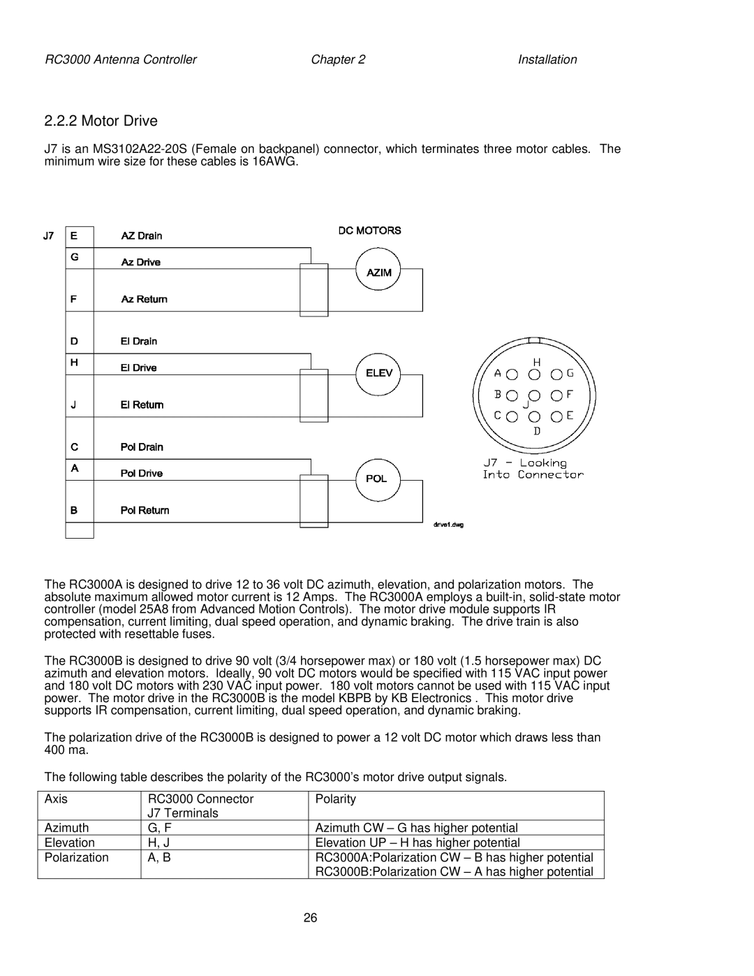
J7 is an
The RC3000A is designed to drive 12 to 36 volt DC azimuth, elevation, and polarization motors. The absolute maximum allowed motor current is 12 Amps. The RC3000A employs a
The RC3000B is designed to drive 90 volt (3/4 horsepower max) or 180 volt (1.5 horsepower max) DC azimuth and elevation motors. Ideally, 90 volt DC motors would be specified with 115 VAC input power and 180 volt DC motors with 230 VAC input power. 180 volt motors cannot be used with 115 VAC input power. The motor drive in the RC3000B is the model KBPB by KB Electronics . This motor drive supports IR compensation, current limiting, dual speed operation, and dynamic braking.
The polarization drive of the RC3000B is designed to power a 12 volt DC motor which draws less than 400 ma.
The following table describes the polarity of the RC3000’s motor drive output signals.
Axis | RC3000 Connector | Polarity |
| J7 Terminals |
|
Azimuth | G, F | Azimuth CW – G has higher potential |
Elevation | H, J | Elevation UP – H has higher potential |
Polarization | A, B | RC3000A:Polarization CW – B has higher potential |
|
| RC3000B:Polarization CW – A has higher potential |
26