RC3000 Antenna Controller | Chapter 2 | Installation |
STEP 4. Elevation Scale Factor Calibration
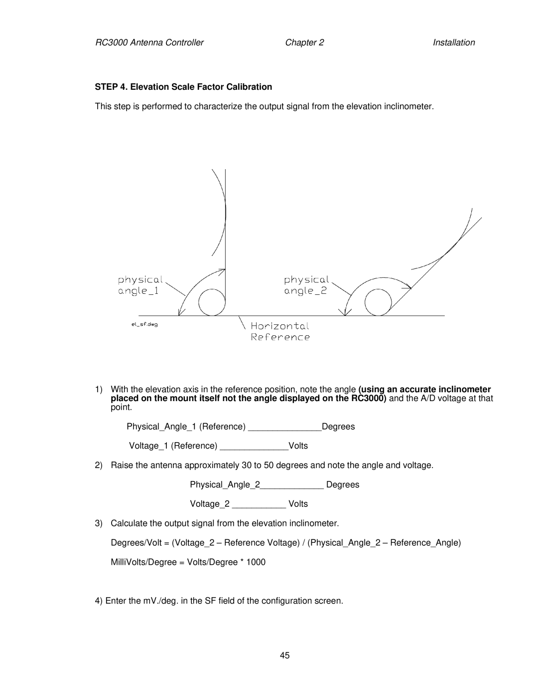
This step is performed to characterize the output signal from the elevation inclinometer.
1)With the elevation axis in the reference position, note the angle (using an accurate inclinometer placed on the mount itself not the angle displayed on the RC3000) and the A/D voltage at that point.
Physical_Angle_1 (Reference) _______________Degrees
Voltage_1 (Reference) ______________Volts
2)Raise the antenna approximately 30 to 50 degrees and note the angle and voltage. Physical_Angle_2_____________ Degrees
Voltage_2 ___________ Volts
3)Calculate the output signal from the elevation inclinometer.
Degrees/Volt = (Voltage_2 – Reference Voltage) / (Physical_Angle_2 – Reference_Angle) MilliVolts/Degree = Volts/Degree * 1000
4)Enter the mV./deg. in the SF field of the configuration screen.
45