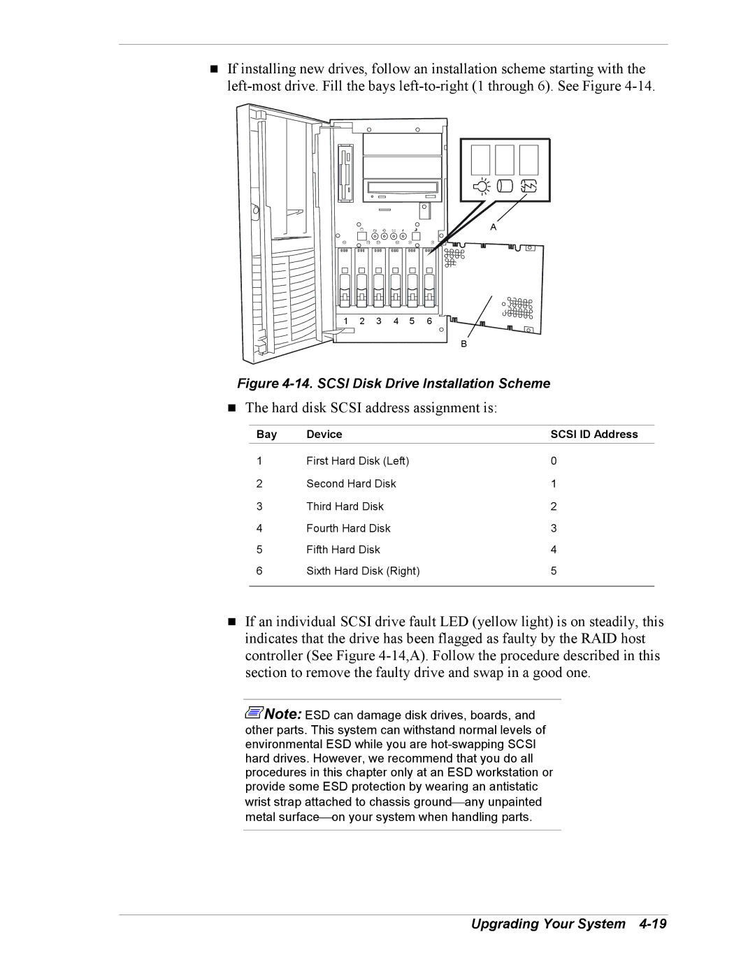
!If installing new drives, follow an installation scheme starting with the
A
0 | 1 | 2 | 3 | 4 | 5 |
1 2 3 4 5 6
B
Figure 4-14. SCSI Disk Drive Installation Scheme
!The hard disk SCSI address assignment is:
Bay | Device | SCSI ID Address |
|
|
|
1 | First Hard Disk (Left) | 0 |
2 | Second Hard Disk | 1 |
3 | Third Hard Disk | 2 |
4 | Fourth Hard Disk | 3 |
5 | Fifth Hard Disk | 4 |
6 | Sixth Hard Disk (Right) | 5 |
|
|
|
!If an individual SCSI drive fault LED (yellow light) is on steadily, this indicates that the drive has been flagged as faulty by the RAID host controller (See Figure
![]() Note: ESD can damage disk drives, boards, and other parts. This system can withstand normal levels of environmental ESD while you are
Note: ESD can damage disk drives, boards, and other parts. This system can withstand normal levels of environmental ESD while you are
