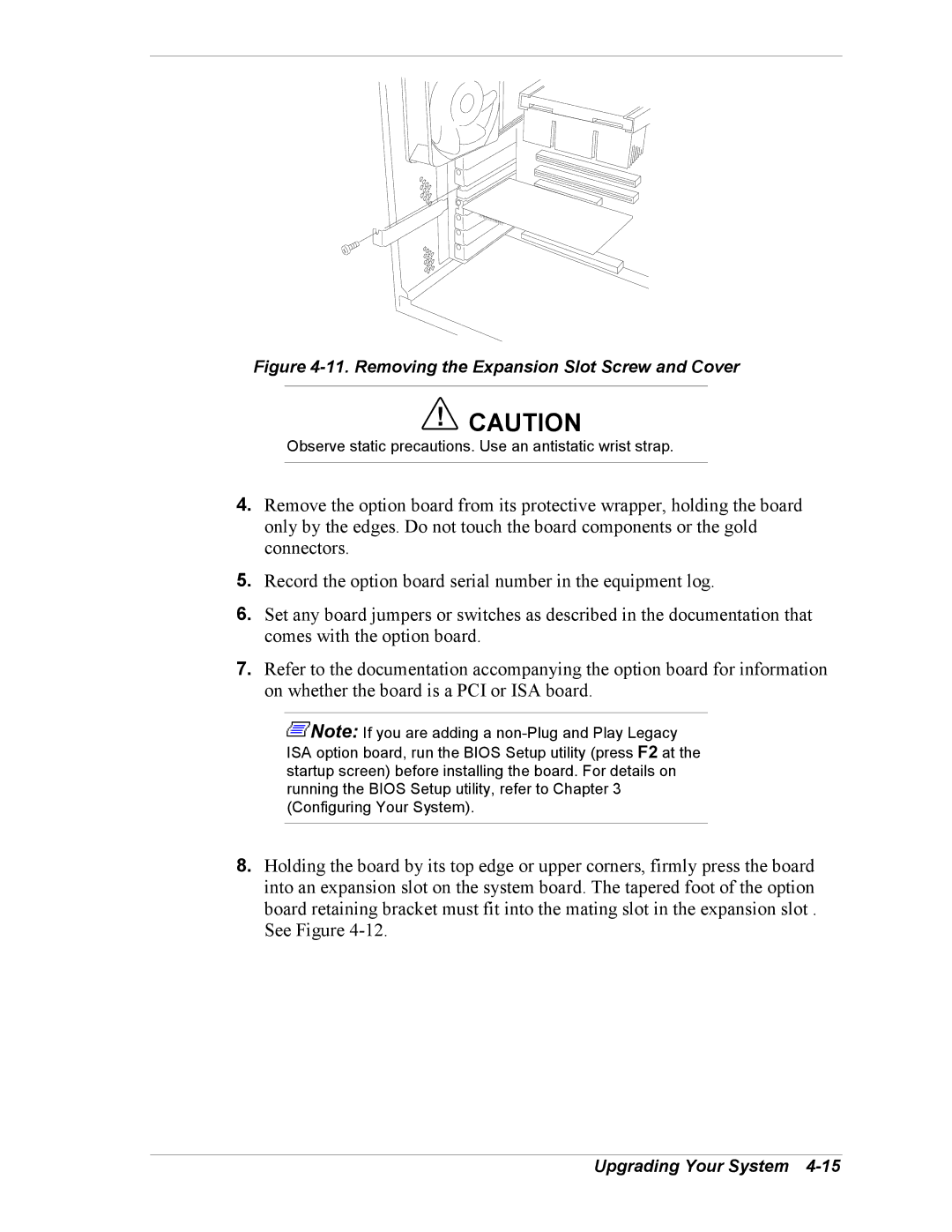
Figure 4-11. Removing the Expansion Slot Screw and Cover
!CAUTION
Observe static precautions. Use an antistatic wrist strap.
4.Remove the option board from its protective wrapper, holding the board only by the edges. Do not touch the board components or the gold connectors.
5.Record the option board serial number in the equipment log.
6.Set any board jumpers or switches as described in the documentation that comes with the option board.
7.Refer to the documentation accompanying the option board for information on whether the board is a PCI or ISA board.
![]() Note: If you are adding a
Note: If you are adding a
8.Holding the board by its top edge or upper corners, firmly press the board into an expansion slot on the system board. The tapered foot of the option board retaining bracket must fit into the mating slot in the expansion slot . See Figure