Intel 5800/120Ld manual Option Boards, Installation Considerations, Installing an Option Board

Models: 5800/120Ld

1 168
Download 168 pages 47.67 Kb
Page 82
Image 82

Option Boards

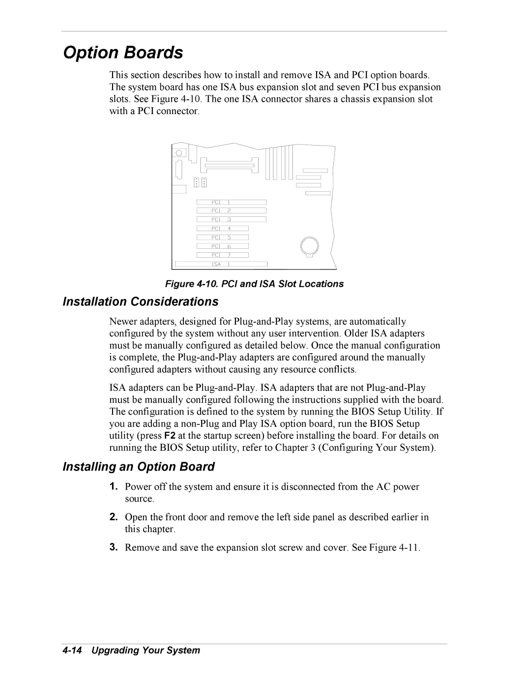
This section describes how to install and remove ISA and PCI option boards. The system board has one ISA bus expansion slot and seven PCI bus expansion slots. See Figure 4-10. The one ISA connector shares a chassis expansion slot with a PCI connector.

Figure 4-10. PCI and ISA Slot Locations

Installation Considerations

Newer adapters, designed for Plug-and-Play systems, are automatically configured by the system without any user intervention. Older ISA adapters must be manually configured as detailed below. Once the manual configuration is complete, the Plug-and-Play adapters are configured around the manually configured adapters without causing any resource conflicts.

ISA adapters can be Plug-and-Play. ISA adapters that are not Plug-and-Play must be manually configured following the instructions supplied with the board. The configuration is defined to the system by running the BIOS Setup Utility. If you are adding a non-Plug and Play ISA option board, run the BIOS Setup utility (press F2 at the startup screen) before installing the board. For details on running the BIOS Setup utility, refer to Chapter 3 (Configuring Your System).

Installing an Option Board

1.Power off the system and ensure it is disconnected from the AC power source.

2.Open the front door and remove the left side panel as described earlier in this chapter.

3.Remove and save the expansion slot screw and cover. See Figure 4-11.

4-14 Upgrading Your System

Page 82
Image 82
Intel 5800/120Ld manual Option Boards, Installation Considerations, Installing an Option Board