JBL SIS Products Group
Introduction
Introduction
Setup
Getting Started
Basic Operation
Troubleshooting & Maintenance
Mode Adjust
Audio Controls
Appendix
English Important Safety Instructions
Español Instrucciones DE Seguridad Importantes
Importanti Norme DI Sicurezza
Dansk Vigtig Information OM Sikkerhed
Norsk Viktig Informasjon OM Sikkerhet
DE Auspacken und Überprüfung
US Unpacking and Inspection
ES Desembalaje e inspección
FR Contenu de l’emballage et inspection
Getting Started
About the SDP-5
Getting Started
Highlights
Do Not
Installation Considerations
To replace the remote control batteries
Remote Control Battery Installation
Basic Operation
Front Panel Overview
Standby Button
Front Panel Display
Mode and Buttons
Volume Knob
To use the volume knob to adjust Main Zone volume level
To use the volume knob to adjust Zone 2 volume level
Main Zone Input Selection Buttons
Mute Button
Main Zone Off Button
Zone 2 Input Selection Buttons
AC Input Connector
Power Switch
Digital Audio Input Connectors S/PDIF
Digital Audio Output Connector S/PDIF
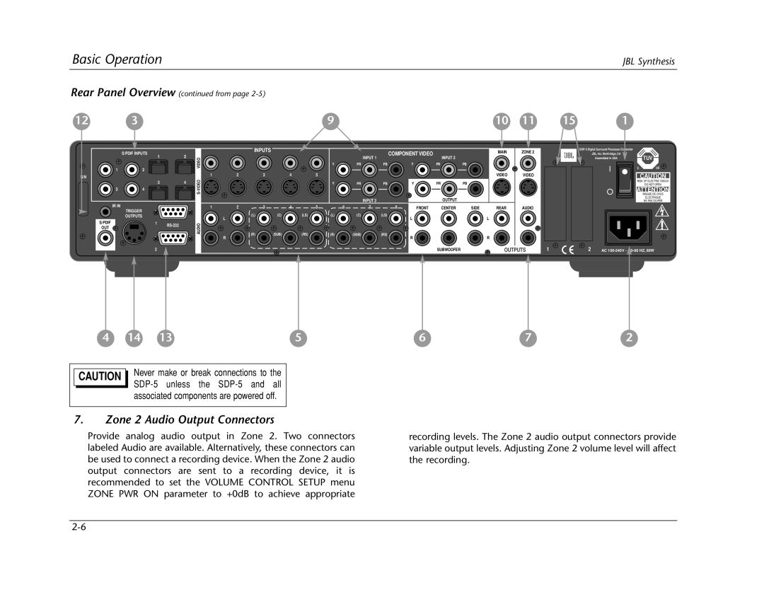
Rear Panel Overview from
Zone 2 Audio Output Connectors
Main Zone Video Output Connectors
Video Input Connectors
Zone 2 Video Output Connectors
RS-232 Connectors
Main Menu
Remote Control Overview
Operation Considerations
Menu Navigation
Menu Options
Arrow Navigation Functions
Parameter Drop-Down Menus
Menu Parameters
To select the desired setting on a parameter drop-down menu
To adjust a parameter setting with a horizontal bar graph
Horizontal Bar Graphs
Command Bank Activation
Command Matrix
To activate the Zone 2 or Shift command bank
Button Main Zone Shift
Scroll upward Increase Decrease Adjust the Audio
DVD2
Basic Operation
Shift-dts
Shift-DOLBY
Shift-THX
Understanding the Zones
Main Zone Two-Line Status
TWO-LINE Status
Zone 2 Two-Line Status
Status Menus
Status menus
Parameter Possible Settings
2CH Status
Dolby D Status
1a Bypass Status
Dts-ES Status
Digital Status
2CH Bypass Status
BIT Rate
Encoding
Center MIX LVL
Channels
Input Type
Input
MIX Room
Mode
Basic Operation
Setup
Volume Controls
Rear Panel Config
Displays
Inputs
Lock Options
Input Setup
Changing Input Names Name
Edit Input Name
To customize the name of the selected input
To restore the factory-default name of the selected input
Restore Default Name
Assigning Audio & Video Input Connectors
Digital
COAX-1 to 4, OPTICAL-1 to 4, None
Please note the following
Assigning Audio & Video Input Connectors from
Auto
Anlg in LVL
Manual
Auto Gain
18 to +12dB
Level Meters
Video
COMPOSITE-1 to 5, S-VIDEO-1 to 5, None
Component
Selecting Preferred Listening Modes
Selecting Preferred Listening Modes from
When the 2-CH parameter is set to USE Last
Dolby D
When the Dolby D parameter is set to USE Last
Dts-ES
When the dts-ES parameter is set to USE Last
Main Advanced
Configuring Advanced Zone Settings
Input Select
Digital Analog Auto
Input Select Parameter Settings
ON, OFF
CH Anlg BYP
Video
Video OSD
Component OSD
DIGITAL, ANLG, Dmix
ZONE2
ZONE2 in Parameter Settings
Digital
Anlg Analog Dmix Downmix
Speaker Setup
Custom Speaker Setups
Determining Crossover Points
Highpass Filter
Default Possible Parameter Setting Settings
Front L/R
FULL, 30Hz to 120Hz, THX 80Hz
FULL, 30Hz to 120Hz, THX 80Hz, None
Center
Side L/R
Rear L/R
Subwoofer
BGC Boundary Gain Compensation
THX ULTRA2 SUB
ASA Advanced Speaker Array
THX ULTRA2 SUB OFF ON, OFF BGC ASA Apart
Synthesis 7-CHANNEL Speaker Setups
THX 80Hz, None
JBL Synthesis 7-Channel Speaker Setups from
Measuring Speaker Distances
Side Left & Right
Measuring Speaker Distances from
Rear Left & Right
Units
Internal Noise Test
Calibrating Output Levels
Internal Noise Test from
Dacs Calibration
Channel Dolby Digital Dts-ES
Sources
18.0 to +12.0dB
Front Left & Right
Side Left & Right
Rear Left & Right
Subwoofer
CAL Noise
Bass Peak Limiter
SUB Limiter
SUB Limit ADJ
75 to 120dB
Rear Panel Config
Stereo Inputs
ST. & 1 5.1 Anlg
ST. & 2 5.1 Anlg
Sync Delay
Display Setup
To customize the name of the SDP-5
Edit Custom Name
Status
ON-SCREEN Display Setup
Format
Position
Remote State
Background
Status
Front Panel Display Setup
Brightness
100%, 75%, 50%, 25%
Main PWR on
Volume Control Setup
Mute Level
Zone PWR on
Selecting the Setup menu Trigger option opens
Trigger Setup menu shown at the right, which can
Be used to configure the trigger output connector
Program Operation Parameters ON, OFF
Lock Options
Modes
Audio Cntrl
Setup
Audio Controls
Audio Controls
Default Possible Parameter Value Settings
Bass
Treble
Bass Parameter Settings Treble Parameter Settings
Tilt EQ
Loudness
To +3.0dB
Tilt EQ Parameter Settings Loudness Parameter Settings
Fader
Balance
ZONE2 Balance
To to R
Mode Adjust
Mode Adjust
Listening Mode Activation
Listening modes can be activated with
Mode and Buttons
Preferred Listening Mode Selection Parameters
Mode Family Selection Buttons
Listening Mode Descriptions
Option Default Possible Parameter Setting Settings
L7 Film
L7 TV
L7 Music Surr
L7 Music
Parameter Setting Settings
Option Default
Dolby Plii + THX
Dolby Plii Movie
Dolby Plii Music
Dolby PRO Logic
Option Parameter
Dts NEO6 Music
Dts NEO6 Film
Concert Hall
Nightclub
Cathedral
Church
To calibrate the Panorama listening mode
Panorama
Panorama Calibration
Speaker Angle
Source
Listener POS
Party
Channel
+0dB OFF, -30 to +12dB
Mono Logic
Mono Surround
Mono
L7 TV
L7 Film
THX, 5.1 THX ULTRA2, & 5.1 THX SurEX
L7 Music
THX SurEX
Channel Channel Surround EX-Encoded
Dolby Digital & Dolby Digital EX
THX Music
Dolby Digital Digital EX Flagged Digital EX Non-Flagged
Channel Channel Dolby
2-CHANNEL
Mono
Mono Surr
Dts-ES Decoding
Channel dts
Dts
Dts-ES L7 Music
Dts-ES L7 Film
Dts THX ULTRA2 & dts-ES THX
+0.0dB 10.0 to +0.0dB
Dts THX Music
Dts-ES 2-CHAN
Dts-ES
2CH Bypass
1a Bypass
Spkr Enhance
Bass Content
Academy Filter
Auto Azimuth
Calibration
Bass RT
Center Depth
Center MIX
Custom VS Preset
Listening Mode Menu Option & Parameter Descriptions
Dimension
Effect LVL
EX Decoding
Front Steering
Input Balance
Output Levels
Reset Mode
PRE-DELAY
Panorama
RE-EQUALIZER
Size
Reset Mode
Rolloff
Sound Stage
SUB Level
Speech Detect
Surr Rolloff
Surround DLY
Surround EX
Surround MIX
Vocal Enhance
Troubleshooting & Maintenance
Troubleshooting
Routine Maintenance
SDP-5 is powered on, but there is no video
RF interference is present in the audio or video
SDP-5 is exhibiting erratic behavior
To restore factory-default settings
Restoring FACTORY-DEFAULT Settings
Appendix
Audio Input & Output Connectors
Specifications
Main Zone Audio Performance
Zone 2 Audio Performance
Video Input & Output Connectors
Specifications are subject to change without notice
Composite & S-video Performance
Component Video Performance
Menu Tree
Declaration of Conformity
Input Setup DVD1 DVD2 SAT VCR Tuner AUX
JBL
None DVD1 Component
Menu Tree from page A-7
Are automatically set
Menu Tree from page A-9
Party Output Levels Custom Channel SUB Level
Menu Tree from page A-11
Surround DLY
DVD1 DVD2 SAT VCR Tuner AUX
Installation Worksheet Input Setup
Settings
Volume Control
Display Setup
Setup
Trigger Setup