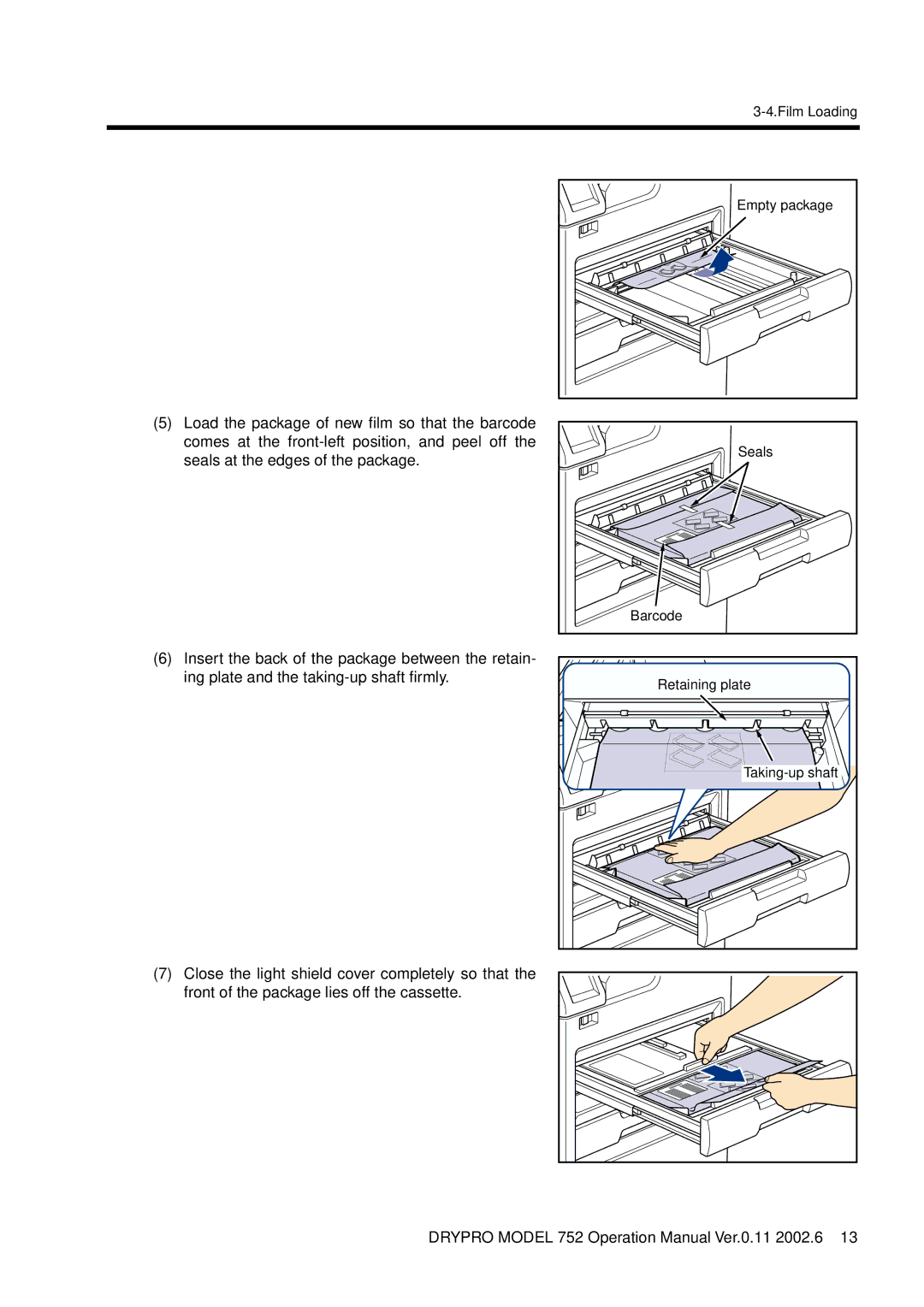
LASER IMAGER
DRYPRO model
CODE NO 0463 UL, 0467 CE
KONICACORPORATION
Blank page
Table of Contents
DRY LASER IMAGER DRYPRO MODEL
Introduction
Symbol mark
Descriptions of Symbol Mark
Descriptions of symbol mark
Descriptions on warning caution label
Descriptions on Warning Label
Warning Label
1 Front
Warning Label Location
2 Rear
Cautions on installation
Safety Caution
Cautions on transporting, storing temporally, and servicing
Cautions on use
otherwise, dust may be accumulated, resulting in heating or a fire
Disposal Precaution
Precaution
Precaution on Installation Location
1. Name of Each Component
Control panel Start switch Upper tray Lower tray Front cover
1-1. Main Body
Front View
Power cable
Power connector
Rear View
Air outlet
Bins Inlet guide Sorter left cover Front cover
1-2. Sorter LiS-752 option
2. Structure
3-1. Control Panel
3. How To Operate
Description on screen
3-2. Start-up Operation
Start switch
Breaker
Touch WAKE UP on the control panel
Power saving mode
3-3. Shut-down Operation
When START TIMER is set to ON
Press the start switch to re-start the equip- ment
3-4.Film Loading
3-4. Film Loading
Film loading screen
Seals
Empty package
Barcode
Retaining plate
9 Push the tray to the back until it is locked
Load the film by referring to Steps 2 or later
4-1. Function of Maintenance Mode
4. Maintenance Mode
Start-up maintenance mode
4-2. Switching Maintenance Mode
Shut-down maintenance mode
Setting START TIMER Function
4-3. How To Operate Maintenance Mode
Setting Date/Time TIME SET
Re-printing Printed Page PREVIOUS PRINT
The print data on the specified page will be queued
9 Touch on the upper part of the screen
8 Touch a LUT name you wish to apply for printing
11 Select NEGA/POSI by touching NEGA or POSI
Calibrating Density CALIBRATION
The DRYPRO has the automatic density calibration function that perform the density calibration automatically after a lapse of the specified time or specified number of printing. Instead of performing automatic calibration, you can make CALIBRA- TION appear on the screen to show you that the calibration needs performing depending on the settings at installation
TEST PRINT
5 Touch on the upper part of the screen
4-3.How To Operate Maintenance Mode
14 Touch EXIT to end the maintenance mode
9 Select NEGA/POSI by touching NEGA or POSI
10 Touch on the upper part of the screen
Each frame of the SMPTE pattern for this device which is printed out by TEST PRINT consists of 16-step wedge, SMPTE pattern, and 1024-step gray scale. Measure the density of the 16-step wedge or SMPTE pattern and use it for the density control
Opening/closing front cover COVER OPEN
The PANEL ADJUST screen will appear
Adjusting control panel PANEL ADJUST
The maintenance menu screen will re-appear
The touch position adjustment screen will appear
3 Touch OK
Clearing queued print data QUEUE CLEAR
4 Touch OK on the confirm message
The COLD START function re-starts the device
COLD START
1 Touch FILM DATA on the maintenance menu screen
Confirming and setting film count data
Confirming film count data
month, touch MONTHLY
The FILM DATA SETUP screen will appear
Follow the procedure below to set the film count preferences
The setting becomes valid, and the film count data screen re- appears
If you wish to cancel the settings, touch CANCEL
Setting print preference
Sets the bin in the sorter option into which the
12 Select the item to be printed as the stamp with STAMP SELECT
16 Sets the format of date to be printed on the film
4-3.How To Operate Maintenance Mode
Setting user LUT
1 Touch the user LUT name to be set on the LUT select screen
2 Touch LUT LIBRARY
Creating user LUT
4-3.How To Operate Maintenance Mode
8 After the settings are complete, touch OK
6 Touch EDIT on the LUT data screen
Confirming the LUT curve
Setting power saving mode
4-3.How To Operate Maintenance Mode
6 After the settings are complete, touch OK
5-1. Error Display and Remedy
5. Troubleshooting
page
page
Page
5-2.Resetting Errors
5-2. Resetting Errors
When an error cannot be reset
If ERROR RESET cannot function by clearing a queued error, follow the procedure below to re-start the device
When TRAY OPEN is displayed
5-3. Removing Jam
When COVER OPEN is displayed
When SORTER COVER is displayed
Jam in tray
Film jam between decent transport section and exposure section
Green lever
Film jam between exposure section and elevator transport section
Film jam between HPRO section and cooling/discharge section
Caution on High Temperatures
1 Open the inlet guide, and remove jammed films if there are any
Film jam in sorter
58 DRYPRO MODEL 752 Operation Manual Ver.0.11
4 Lift the handle of the sorter left cover to remove it
3 Remove jammed films if they remain
5 Open the film transport guide, and remove jammed films if they remain
Sorter left cover
6 Put the film transport guide back, and remove the sorter left cover
Guide pins
Film transport guide
lower
5-4.When Film Fails to be Loaded
5-4. When Film Fails to be Loaded
Rail
5 Open the light shield cover of the tray
5-4.When Film Fails to be Loaded
14 Touch OK 15 Touch EXIT to end the maintenance mode
13 Touch the key of the tray in which you wish to re- load the film
16 Touch FILM SET
17 When the tray pops out slightly, press in it until it locks
6-1. Periodical Maintenance and Inspection
6. Service and Maintenance
Outer cover of the main unit
Inside of main unit
Caution on High Temperatures
6-2. Replacing FILTER
Other service and maintenance
6-3. Service and Maintenance Schedule
Servicing by a user
Confirming maintenance and maintenance display
When connected to the Regius
7. Specifications
When connected to any other than
the Regius
Sorter Option Specifications
Time zone and code No. table
Appendix
2.Handling and Storage of Developed Film
1.Handling and Storage of Unexposed Film
HANDLING AND STORAGE OF DRY FILM
Blank page
Blank page