3-2. Start-up Operation
Follow the procedure below to turn on the power of the equipment.
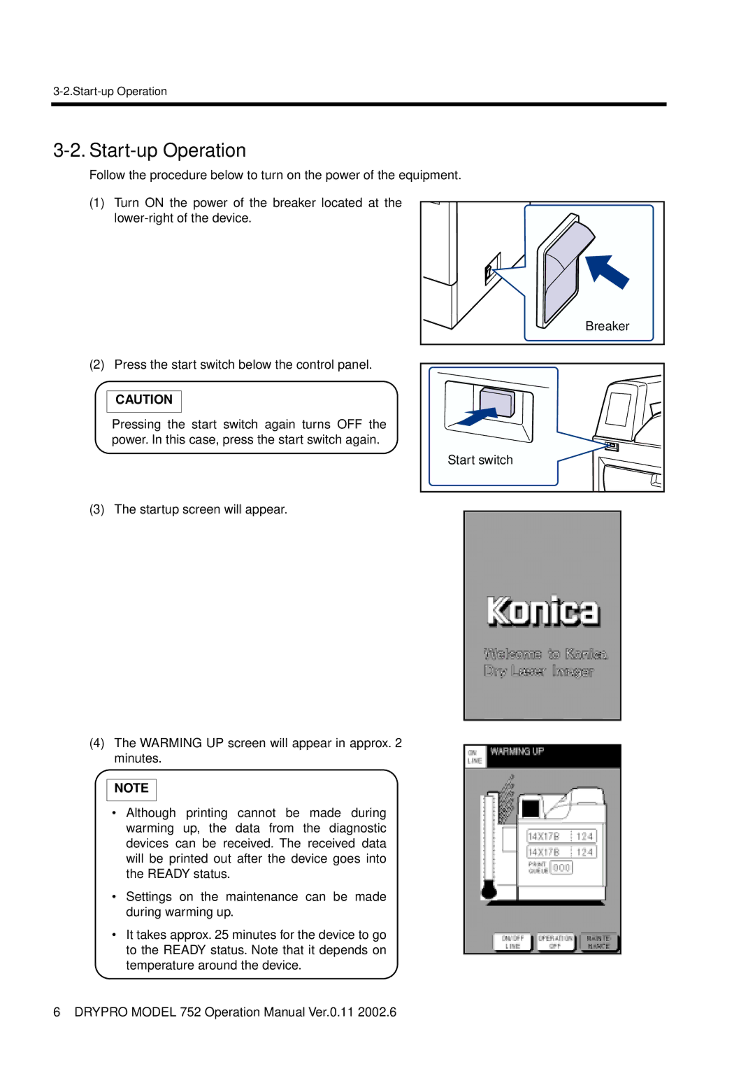
(1)Turn ON the power of the breaker located at the
(2) Press the start switch below the control panel.
CAUTION
Pressing the start switch again turns OFF the power. In this case, press the start switch again.
(3) The startup screen will appear.
Breaker |
Start switch |
(4)The WARMING UP screen will appear in approx. 2 minutes.
NOTE
•Although printing cannot be made during warming up, the data from the diagnostic devices can be received. The received data will be printed out after the device goes into the READY status.
•Settings on the maintenance can be made during warming up.
•It takes approx. 25 minutes for the device to go to the READY status. Note that it depends on temperature around the device.
6 DRYPRO MODEL 752 Operation Manual Ver.0.11 2002.6