5-4.When Film Fails to be Loaded
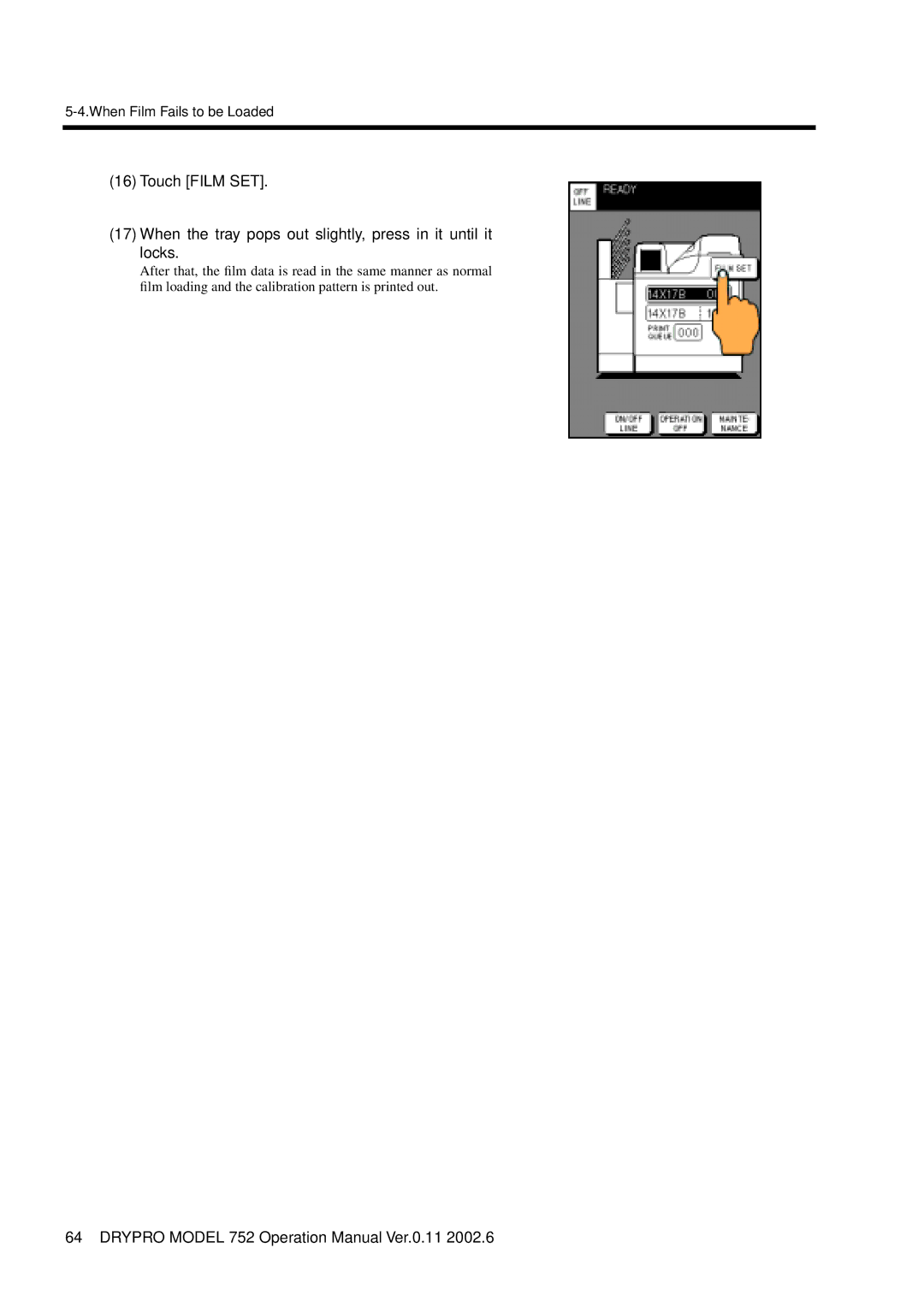
(16)Touch [FILM SET].
(17)When the tray pops out slightly, press in it until it locks.
After that, the film data is read in the same manner as normal film loading and the calibration pattern is printed out.
64 DRYPRO MODEL 752 Operation Manual Ver.0.11 2002.6