Return to Section TOC Return to Master TOC
Return to Section TOC Return to Master TOC
Return to Section TOC Return to Master TOC
Return to Section TOC Return to Master TOC
|
|
| INSTALLATION |
|
|
| ||||||||
|
|
|
|
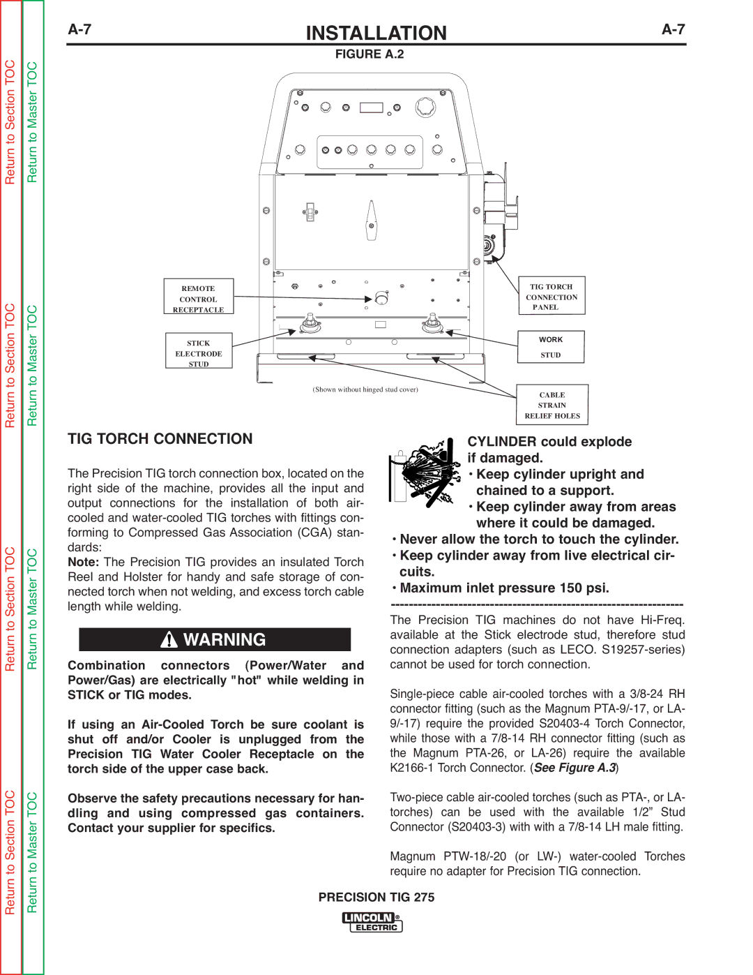
| FIGURE A.2 |
|
|
|
| |||||
|
|
|
|
|
|
|
|
|
|
|
|
|
|
|
|
|
|
|
|
|
|
|
|
|
|
|
|
|
|
|
|
|
|
|
|
|
|
|
|
|
|
|
|
|
|
|
|
|
|
|
|
|
|
|
|
|
|
|
|
|
|
|
|
|
|
|
|
|
|
|
|
|
|
|
|
|
|
|
|
|
|
|
|
|
|
|
|
|
|
|
|
|
|
|
|
|
|
|
|
|
|
|
|
|
| TIG TORCH |
| CONNECTION |
| PANEL |
STICK | WORK |
| WORK |
| STUD |
(Shown withoutFIGUREhinged studA cover)
CABLE
STRAIN
CYLINDERRELIEFcouldHOLES explode if damaged.
• Keep cylinder upright and chained to a support.
• Keep cylinder away from areas where it could be damaged.
• Never allow the torch to touch the cylinder.
• Keep cylinder away from live electrical cir- cuits.
• Maximum inlet pressure 150 psi.
The Precision TIG machines do not have
PRECISION TIG 275
