Return to Section TOC Return to Master TOC
F-60 TROUBLESHOOTING & REPAIRF-60
SCR REMOVAL AND REPLACEMENT (continued)
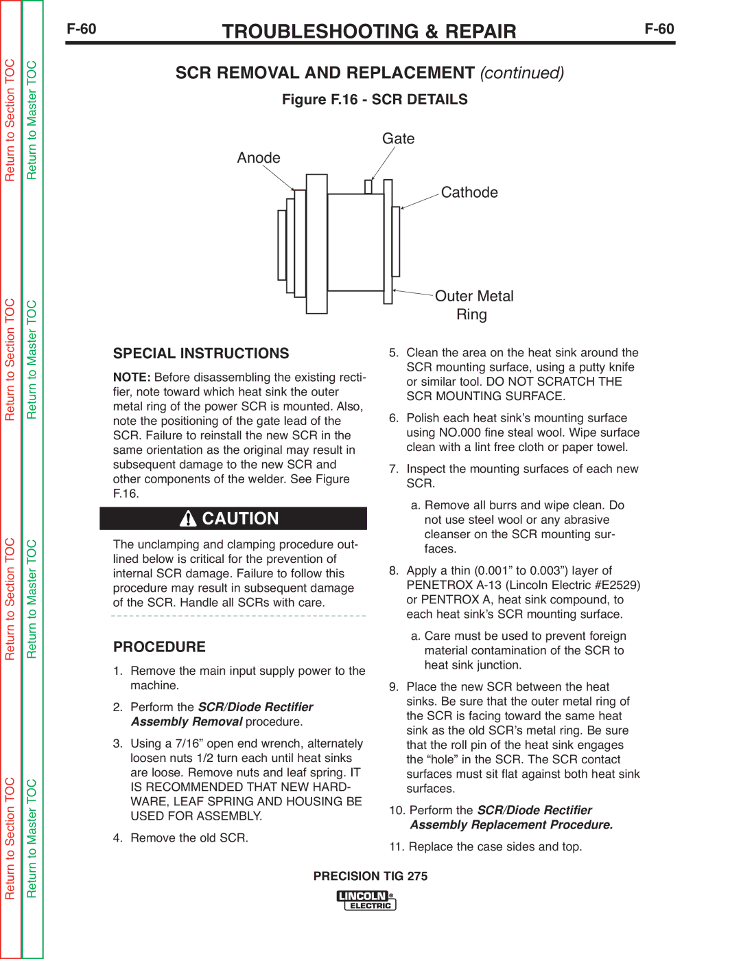
Figure F.16 - SCR DETAILS
Gate
Cathode
Return to Section TOC Return to Master TOC
Return to Section TOC Return to Master TOC
Return to Section TOC Return to Master TOC
|
|
|
|
|
|
|
|
|
|
|
|
|
|
| Outer Metal |
|
|
|
|
|
|
|
|
|
|
|
|
|
|
| |
|
|
|
|
|
|
|
|
|
|
|
|
|
|
| |
|
|
|
|
|
|
|
|
|
|
|
|
|
|
| |
|
|
|
|
|
|
|
|
|
|
|
|
|
|
| |
|
|
|
|
|
|
|
|
|
|
|
|
|
|
| |
|
|
|
|
|
|
|
|
|
|
|
|
|
|
| |
|
|
|
|
|
|
|
|
|
|
|
|
|
|
| Ring |
|
|
|
|
|
|
|
|
|
|
|
|
|
|
| |
SPECIAL INSTRUCTIONS |
|
| |||||||||||||
5. | Clean the area on the heat sink around the | ||||||||||||||
NOTE: Before disassembling the existing recti- |
|
| SCR mounting surface, using a putty knife | ||||||||||||
fier, note toward which heat sink the outer |
|
| or similar tool. DO NOT SCRATCH THE | ||||||||||||
metal ring of the power SCR is mounted. Also, | 6. | SCR MOUNTING SURFACE. | |||||||||||||
note the positioning of the gate lead of the | Polish each heat sinkʼs mounting surface | ||||||||||||||
SCR. Failure to reinstall the new SCR in the |
|
| using NO.000 fine steal wool. Wipe surface | ||||||||||||
same orientation as the original may result in | 7. | clean with a lint free cloth or paper towel. | |||||||||||||
subsequent damage to the new SCR and | Inspect the mounting surfaces of each new | ||||||||||||||
other components of the welder. See Figure |
|
| SCR. | ||||||||||||
F.16. |
|
|
|
|
|
|
|
|
|
|
|
|
| a. Remove all burrs and wipe clean. Do | |
|
| CAUTION |
|
|
| not use steel wool or any abrasive | |||||||||
|
|
|
| cleanser on the SCR mounting sur- | |||||||||||
The unclamping and clamping procedure out- |
|
| |||||||||||||
lined below is critical for the prevention of | 8. | faces. | |||||||||||||
internal SCR damage. Failure to follow this | Apply a thin (0.001” to 0.003”) layer of | ||||||||||||||
procedure may result in subsequent damage |
|
| PENETROX | ||||||||||||
of the SCR. Handle all SCRs with care. |
|
| or PENTROX A, heat sink compound, to | ||||||||||||
|
| each heat sinkʼs SCR mounting surface. | |||||||||||||
PROCEDURE |
|
|
|
|
|
|
|
|
|
|
|
| a. Care must be used to prevent foreign | ||
|
|
|
|
|
|
|
|
|
|
|
| material contamination of the SCR to | |||
1. | Remove the main input supply power to the | 9. | heat sink junction. | ||||||||||||
2. | machine. |
|
|
|
|
|
|
|
|
|
|
| Place the new SCR between the heat | ||
Perform the SCR/Diode Rectifier |
|
| sinks. Be sure that the outer metal ring of | ||||||||||||
| A sembly Removal | procedure. |
|
| the SCR is facing toward the same heat | ||||||||||
3. |
|
|
|
| sink as the old SCRʼs metal ring. Be sure | ||||||||||
Using a 7/16” open end wrench, alternately |
|
| that the roll pin of the heat sink engages | ||||||||||||
| loosen nuts 1/2 turn each until heat sinks |
|
| the “hole” in the SCR. The SCR contact | |||||||||||
| are loose. Remove nuts and leaf spring. IT |
|
| surfaces must sit flat against both heat sink | |||||||||||
| IS RECOMMENDED THAT NEW HARD- |
|
| surfaces. | |||||||||||
| WARE, LEAF SPRING AND HOUSING BE | 10. Perform the SCR/Diode Rectifier | |||||||||||||
4. | USED FOR ASSEMBLY. |
|
| Assembly Replacement Procedure. | |||||||||||
Remove the old SCR. | 11. Replace the case sides and top. | ||||||||||||||
|
|
|
|
|
|
|
| PRECISION TIG 275 | |||||||