to Section TOC Return to Master TOC
F-46 TROUBLESHOOTING & REPAIRF-46
HIGH VOLTAGE TRANSFORMER
REMOVAL AND REPLACEMENT (continued)
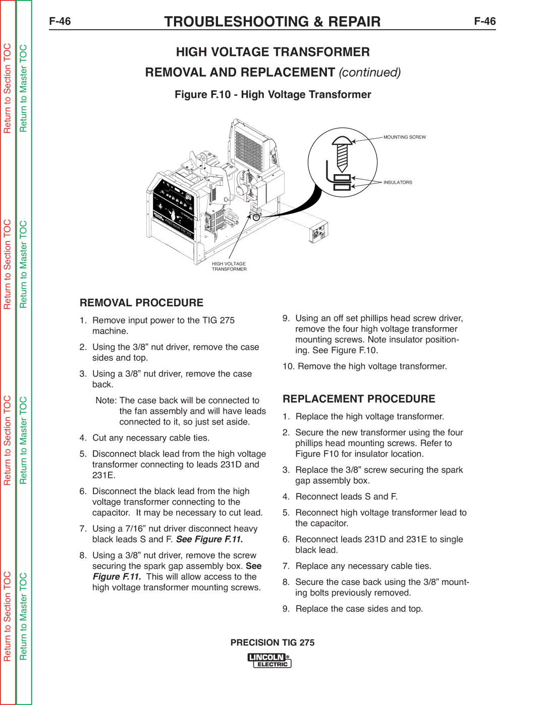
Figure F.10 - High Voltage Transformer
Return
to Section TOC to Master TOC
! | WARNING |
| |
| ON |
| POWER |
| OFF |
LI |
|
NC |
|
OL | |
ELE | N |
| CT |
| RIC |
D | AC~ |
|
|
|
C |
|
|
| |
|
|
| SQUA |
|
|
| featur REW |
| |
|
|
| ing...AVE POW | |
|
| DC |
| MICER S |
|
|
| ROURCE | |
P |
|
| + | STA |
|
|
| RT | |
R |
|
|
| |
| E |
|
|
|
| CI |
|
|
|
| SI |
|
| |
|
| O |
|
|
|
| N TI |
| |
|
|
| G 3 | |
|
|
|
| 75 |
MOUNTING SCREW
![]() INSULATORS
INSULATORS
HIGH VOLTAGE
TRANSFORMER
Return Return
Return to Section TOC Return to Master TOC
Section TOC Master TOC
REMOVAL PROCEDURE
1. Remove input power to the TIG 275 machine.
2. Using the 3/8” nut driver, remove the case sides and top.
3. Using a 3/8” nut driver, remove the case back.
Note: The case back will be connected to the fan assembly and will have leads connected to it, so just set aside.
4. Cut any necessary cable ties.
5. Disconnect black lead from the high voltage transformer connecting to leads 231D and 231E.
6. Disconnect the black lead from the high voltage transformer connecting to the capacitor. It may be necessary to cut lead.
7. Using a 7/16” nut driver disconnect heavy. black leads S and F. See Figure F.11
8. Using a 3/8” nut driver, remove the screw securing the spark gap assembly box. See
This will allow access to the highFi urevoltageF.11. transformer mounting screws.
9.Using an off set phillips head screw driver, remove the four high voltage transformer mounting screws. Note insulator position- ing. See Figure F.10.
10.Remove the high voltage transformer.
REPLACEMENT PROCEDURE
1. Replace the high voltage transformer.
2. Secure the new transformer using the four phillips head mounting screws. Refer to Figure F10 for insulator location.
3. Replace the 3/8” screw securing the spark gap assembly box.
4. Reconnect leads S and F.
5. Reconnect high voltage transformer lead to the capacitor.
6. Reconnect leads 231D and 231E to single black lead.
7. Replace any necessary cable ties.
8. Secure the case back using the 3/8” mount- ing bolts previously removed.
9. Replace the case sides and top.
