Return to Section TOC Return to Master TOC
Return to Section TOC Return to Master TOC
F-24 TROUBLESHOOTING & REPAIRF-24
HIGH FREQUENCY CIRCUIT DISABLE PROCEDURE (continued)
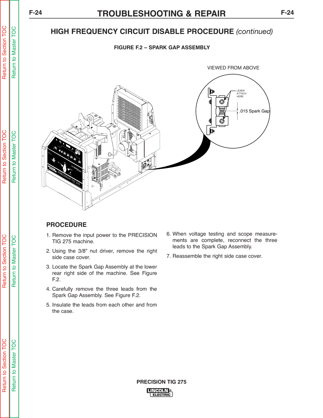
FIGURE F.2 – SPARK GAP ASSEMBLY
VIEWED FROM ABOVE
LEADS |
ATTACH |
HERE |
.015 Spark Gap |
|
|
|
|
| MODE |
|
|
|
|
|
|
|
|
|
|
|
|
|
|
| MINIMUM | DISPLAY |
|
|
|
|
|
|
|
|
|
|
|
|
|
|
|
|
|
|
|
|
|
|
|
| |
|
|
|
|
|
|
|
|
|
| LOCAL |
|
|
|
| |
|
|
|
| AC | BALANCE |
|
|
|
| REMOTE |
|
|
|
| |
|
|
|
|
|
|
|
|
|
|
|
|
| |||
! | WARNING |
|
|
|
|
|
|
|
|
|
|
|
|
| |
|
|
|
|
|
|
|
|
|
|
|
|
|
| ||
|
|
|
|
|
|
|
|
|
|
|
|
|
| MAXIMUM | |
|
|
| ON |
|
|
|
|
|
|
|
|
|
|
|
|
|
| POWER |
|
|
|
|
|
|
|
|
|
|
|
|
|
|
|
| OFF |
| DC | A |
|
|
|
|
|
|
|
|
|
|
|
|
|
|
| C~ |
|
|
|
|
|
|
|
| POSTFLOW |
|
|
|
|
|
|
|
|
| S |
|
|
|
|
|
|
LI |
|
|
|
|
|
|
| QUA | REW |
|
|
|
|
| |
|
|
|
|
|
|
| fea | AVE |
|
|
|
| |||
|
| CO |
|
|
|
|
|
|
| g... | MI | ER S |
|
| |
| N | L |
|
|
|
|
|
|
| POW |
|
| |||
| E |
|
|
|
| DC |
|
|
| CR |
|
| |||
|
| LE | N |
|
|
|
| + |
|
|
| OURCE | |||
|
| CT |
|
|
|
|
|
|
|
|
| S | TA | ||
|
|
| RI | P |
|
|
|
|
|
|
|
|
| ||
|
|
|
| C |
|
|
|
|
|
|
|
|
| TECH RT | |
|
|
|
|
|
| D |
|
|
|
|
|
|
| NOLOGY | |
|
|
|
|
|
| WOH T |
|
|
|
|
|
|
| ||
|
|
|
|
| RE |
|
| INLOEWSEWLIDTICNHG |
|
|
|
|
|
| |
|
|
|
|
| CI |
|
|
|
|
|
|
|
|
| |
|
|
|
|
|
| SI |
|
|
|
|
|
|
|
| |
|
|
|
|
|
|
| O | N | TI |
|
|
|
|
| |
|
|
|
|
|
|
|
|
|
|
|
|
| |||
|
|
|
|
|
|
|
|
|
| TM |
|
|
| ||
|
|
|
|
|
|
|
|
| THELING |
| 3 | 5 | |||
|
|
|
|
|
|
|
|
|
| COLN |
| ||||
|
|
|
|
|
|
|
|
|
|
|
|
| CO | ||
|
|
|
|
|
|
|
|
|
|
|
| ELECTRIC 7 | |||
|
|
|
|
|
|
|
|
|
|
|
|
|
| MPANY | CLEVELAND,O |
|
|
|
|
|
|
|
|
|
|
|
|
|
|
| |
|
|
|
|
|
|
|
|
|
|
|
|
|
|
| HIO USA |
Return to Section TOC Return to Master TOC
PROCEDURE
1. Remove the input power to the PRECISION TIG 275 machine.
2. Using the 3/8” nut driver, remove the right side case cover.
3. Locate the Spark Gap Assembly at the lower rear right side of the machine. See Figure F.2.
4. Carefully remove the three leads from the Spark Gap Assembly. See Figure F.2.
5. Insulate the leads from each other and from the case.
6.When voltage testing and scope measure- ments are complete, reconnect the three leads to the Spark Gap Assembly.
7.Reassemble the right side case cover.
Return to Section TOC Return to Master TOC