Return to Section TOC Return to Master TOC
Return to Section TOC Return to Master TOC
|
| OPERATION | |||||
CONTROLS AND SETTINGS |
| ||||||
The Front Control Panel contains the knobs and switches necessary for adjusting the operation of the Precision | |||||||
TIG 275, with function indicator lights and an electronic display for volts and amps. The components are | |||||||
described below: |
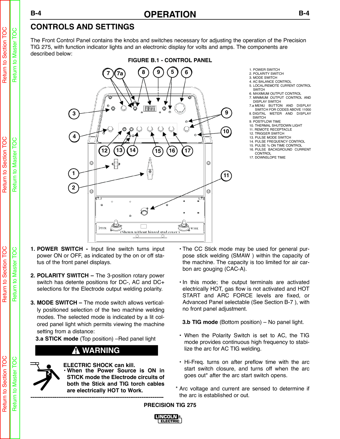
| FIGURE B.1 - CONTROL PANEL |
| ||||
7 | 7a |
| 8 | 9 | 5 | 6 | 1. POWER SWITCH |
| 2. POLARITY SWITCH | ||||||
|
|
|
|
| 3. MODE SWITCH | ||
|
|
|
|
|
|
| 4. AC BALANCE CONTROL |
|
|
|
|
|
|
| 5. LOCAL/REMOTE CURRENT CONTROL |
|
|
|
|
|
|
| SWITCH |
|
|
|
|
|
|
| 6. MAXIMUM OUTPUT CONTROL |
|
|
|
|
|
|
| 7. MINIMUM OUTPUT CONTROL AND |
|
|
|
|
|
|
| DISPLAY SWITCH |
3 |
|
|
|
|
| 9 | 7.a MENU BUTTON AND DISPLAY |
|
|
|
|
| SWITCH FOR CODES ABOVE 11000 | ||
|
|
|
|
| 8. DIGITAL METER AND DISPLAY | ||
|
|
|
|
|
| SWITCH | |
|
|
|
|
|
|
| 9. POSTFLOW TIME |
|
|
|
|
|
| 10 | 10. THERMAL SHUTDOWN LIGHT |
4 |
|
|
|
|
| 11. REMOTE RECEPTACLE | |
|
|
|
|
| 12. TRIGGER SWITCH | ||
|
|
|
|
|
| 13. PULSE MODE SWITCH | |
12 | 13 | 14 |
| 15 | 16 | 17 | 14. PULSE FREQUENCY CONTROL |
| CONTROL | ||||||
|
|
|
|
|
|
| 15. PULSE % ON TIME CONTROL |
|
|
|
|
|
|
| 16. PULSE BACKGROUND CURRENT |
1 |
|
|
|
|
|
| 17. DOWNSLOPE TIME |
|
|
|
|
| 11 |
| |
2 |
|
|
|
|
|
|
|
Return to Section TOC Return to Master TOC
Return to Section TOC Return to Master TOC
1. POWER SWITCH - Input line switch turns input | • The CC Stick mode may be used for general pur- | |
| power ON or OFF, as indicated by the on or off sta- | pose stick welding (SMAW ) within the capacity of |
2. | tus of the front panel displays. | the machine. The capacity is too limited for air car- |
POLARITY SWITCH – The | bon arc gouging | |
| switch has detente positions for | • In this mode; the output terminals are activated |
| selections for the Electrode output welding polarity. | electrically HOT, gas flow is not activated and HOT |
3. MODE SWITCH – The mode switch allows vertical- | START and ARC FORCE levels are fixed, or | |
Advanced Panel selectable (See Section | ||
| ly positioned selection of the two machine welding | no front panel adjustment. |
| modes. The selected mode is indicated by a lit col- | 3.b TIG mode (Bottom position) – No panel light. |
| ored panel light which permits viewing the machine | |
| setting from a distance: | • When the Polarity Switch is set to AC, the TIG |
| 3.a STICK mode (Top position) | mode provides continuous high frequency to stabi- |
| WARNING | lize the arc for AC TIG welding. |
| ELECTRIC SHOCK can kill. | • |
| • When the Power Source is ON in | start switch closure, and turns off when the arc |
| STICK mode the Electrode circuits of | goes out* after the arc start switch opens. |
| both the Stick and TIG torch cables | * Arc voltage and current are sensed to determine if |
| are electrically HOT to Work. | |
the arc is established or out. | ||
| PRECISION TIG 275 | |