DEFINITY Enterprise Communications Server Release 6 | Issue 3 |
Installation and Test for Compact Modular Cabinets | May 1998 |
1 Install and Cable the Cabinets |
|
Install Emergency Transfer Unit and Associated Telephones | Page |
|
|
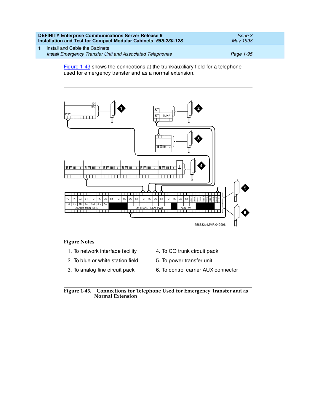
Figure 1-43 shows the connections at the trunk/auxiliary field for a telephone used for emergency transfer and as a normal extension.
10
35
| ST |
2820 | ST EMXR |
|
![]() 7
7
3 | 4 | 5 | 6 | 7 | 8 |
TC | TK | LC | ST | TC | TK | LC ST TC TK LC ST TC TK LC ST | TC TK LC ST | C | N | N | N | C | N | C | N | G | |||||
O | O | O | |||||||||||||||||||
O | C | C | O | C | R | ||||||||||||||||
M | M | M | |||||||||||||||||||
|
|
|
|
|
|
|
|
|
|
|
| 1 | 2 | 1 | 2 | 3 | D | ||||
|
|
|
|
|
|
|
|
|
|
|
| 1 | 2 | 3 | |||||||
|
|
|
|
|
|
|
|
|
|
|
|
|
|
|
|
|
| ||||
1M | 1m | 2M | 2m | 3M | 3m | 3w |
|
|
|
|
|
|
|
|
|
|
|
|
|
| |
| ALARM MONITORS |
|
| EM TRANS RELAY PWR |
|
| ACC PWR |
|
|
|
|
|
|
|
| ||||||
V
|
|
| r758582b MMR 042996 |
Figure Notes |
|
| |
1. | To network interface facility | 4. | To CO trunk circuit pack |
2. | To blue or white station field | 5. | To power transfer unit |
3. | To analog line circuit pack | 6. | To control carrier AUX connector |
