DEFINITY Enterprise Communications Server Release 6 | Issue 3 |
Installation and Test for Compact Modular Cabinets | May 1998 |
1 Install and Cable the Cabinets |
|
Install Emergency Transfer Unit and Associated Telephones | Page |
|
|
![]()
![]() NOTE:
NOTE:
Install the panel so it can be accessed only by authorized personnel. The location must meet standard environmental considerations such as temperature, humidity, and so forth.
2. Verify dial tone is present at each trunk circuit.
EMERGENCY
TRANSFER
PANEL
| POWER |
|
| ||
|
| TRUNK/TEST SWITCHES |
| ||
CIRCUIT |
|
|
| ||
1 |
|
| TRUNK OPTION | ||
2 | 1 |
| |||
1 | LOOP | GROUND | |||
3 |
| ||||
| 2 | START | START | ||
4 | 2 | ||||
|
| ||||
5 |
|
|
|
| |
6 | 3 | BOTH SWITCHES MUST BE |
| ||
7 |
|
| |||
4 | THROWN TO ACTIVATE |
| |||
8 | TRUNK OPTION |
| |||
9 |
|
|
|
| |
10 | 5 |
|
|
| |
12 | TRANSFER TEST SWITCH |
| |||
|
| ||||
| ACTIVATED | NORMAL |
| ||
| OPERATION |
| |||
|
|
|
| ||
| TRUNK IDENTIFICATION |
| |||
TRUNK | EXT | LOC |
| ||
LINE |
|
| |||
|
| 808A |
|
|
| led808a LJK 040896 | |
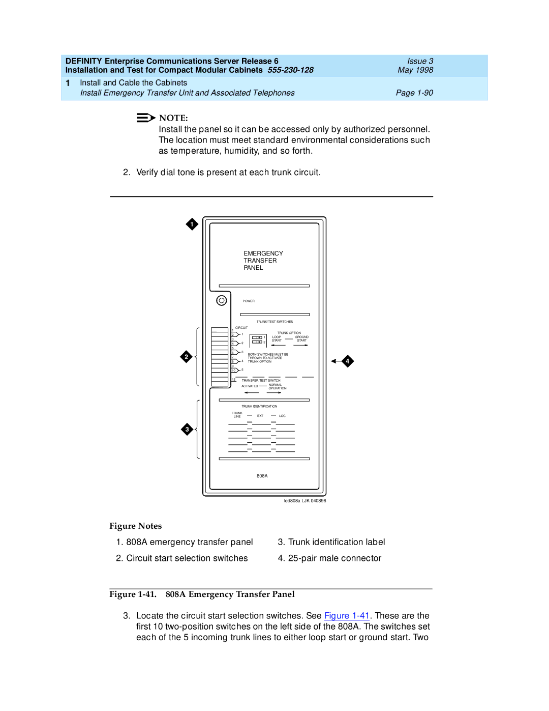
Figure Notes |
|
| |
1. | 808A emergency transfer panel | 3. | Trunk identification label |
2. | Circuit start selection switches | 4. | |
Figure 1-41. 808A Emergency Transfer Panel
3.Locate the circuit start selection switches. See Figure