DEFINITY Enterprise Communications Server Release 6 | Issue 3 |
Installation and Test for Compact Modular Cabinets | May 1998 |
1 Install and Cable the Cabinets |
|
Connect Modem to Telephone Network | Page |
|
|
External Modem Option Settings
The U.S. Robotics Model 839 external modem is the recommended external modem for Release 6 CMC. A locally obtained,
1.If a
2.If no modem is installed, skipt to step 5. If a U.S Robotics Model 839 modem is installed, perform the following.
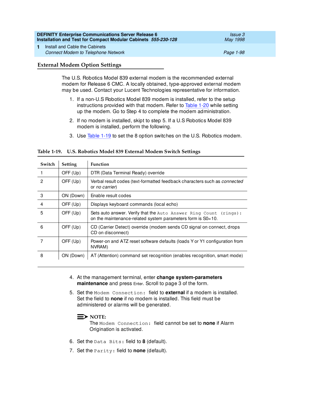
3.Use Table
Table 1-19. U.S. Robotics Model 839 External Modem Switch Settings
Switch | Setting | Function | |
|
|
|
|
1 | OFF (Up) | DTR (Data Terminal Ready) override | |
|
|
|
|
2 | OFF (Up) | Verbal result codes | |
|
| or no carrier) | |
|
|
|
|
3 | ON (Down) | Enable result codes | |
|
|
|
|
4 | OFF (Up) | Displays keyboard commands (local echo) | |
|
|
|
|
5 | OFF (Up) | Sets auto answer. Verify that the Auto Answer Ring Count (rings): | |
|
| on the | |
|
|
|
|
6 | OFF (Up) | CD (Carrier Detect) override (modem sends CD signal on connect, drops | |
|
| CD on disconnect) | |
|
|
|
|
7 | OFF (Up) | ||
|
| NVRAM) | |
|
|
|
|
8 | ON (Down) | AT (Attention) command set recognition (enables recognition, smart mode) | |
|
|
|
|
|
|
|
|
4.At the management terminal, enter change
5.Set the Modem Connection: field to external if a modem is installed. Set the field to none if no modem is installed. This field must be administered or alarms will be generated.
![]()
![]() NOTE:
NOTE:
The Modem Connection: field cannot be set to none if Alarm Origination is activated.
6.Set the Data Bits: field to 8 (default).
7.Set the Parity: field to none (default).
