DEFINITY Enterprise Communications Server Release 6 | Issue 3 |
Installation and Test for Compact Modular Cabinets | May 1998 |
|
|
1Install and Cable the Cabinets
Telephone Pin Designations | Page |
Emergency Transfer and Auxiliary Power
![]()
![]() NOTE:
NOTE:
Only 1 emergency transfer power panel and 1 auxiliary power connection is provided per system.
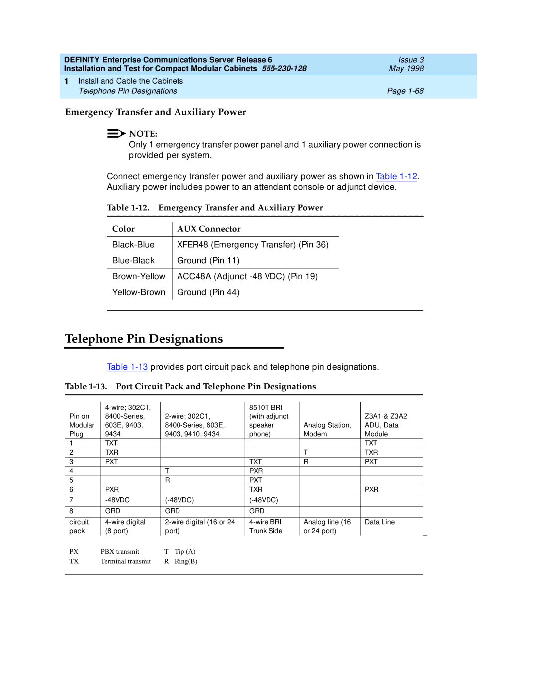
Connect emergency transfer power and auxiliary power as shown in Table
Auxiliary power includes power to an attendant console or adjunct device.
Table
Color | AUX Connector | |
|
|
|
XFER48 (Emergency Transfer) (Pin 36) | ||
Ground (Pin 11) | ||
|
|
|
ACC48A (Adjunct | ||
Ground (Pin 44) | ||
|
|
|
|
|
|
Telephone Pin Designations
Table
Table 1-13. Port Circuit Pack and Telephone Pin Designations
|
|
| 8510T BRI |
|
| |
Pin on | (with adjunct |
| Z3A1 & Z3A2 | |||
Modular | 603E, 9403, | speaker | Analog Station, | ADU, Data | ||
Plug | 9434 | 9403, 9410, 9434 | phone) | Modem | Module | |
1 | TXT |
|
|
|
| TXT |
|
|
|
|
|
|
|
2 | TXR |
|
|
| T | TXR |
|
|
|
|
|
|
|
3 | PXT |
|
| TXT | R | PXT |
4 |
| T |
| PXR |
|
|
5 |
| R |
| PXT |
|
|
|
|
|
|
|
|
|
6 | PXR |
|
| TXR |
| PXR |
|
|
|
|
|
| |
7 |
|
| ||||
|
|
|
|
|
| |
8 | GRD | GRD | GRD |
|
| |
|
|
|
|
|
| |
circuit | Analog line (16 | Data Line | ||||
pack | (8 port) | port) | Trunk Side | or 24 port) |
| |
PX | PBX transmit | T | Tip (A) |
|
|
|
TX | Terminal transmit | R | Ring(B) |
|
|
|
|
|
|
|
|
|
|
