DEFINITY Enterprise Communications Server Release 6 | Issue 3 |
Installation and Test for Compact Modular Cabinets | May 1998 |
1 Install and Cable the Cabinets |
|
Install and Wire Telephones and Other Equipment | Page |
|
|
Adjunct Power Connections
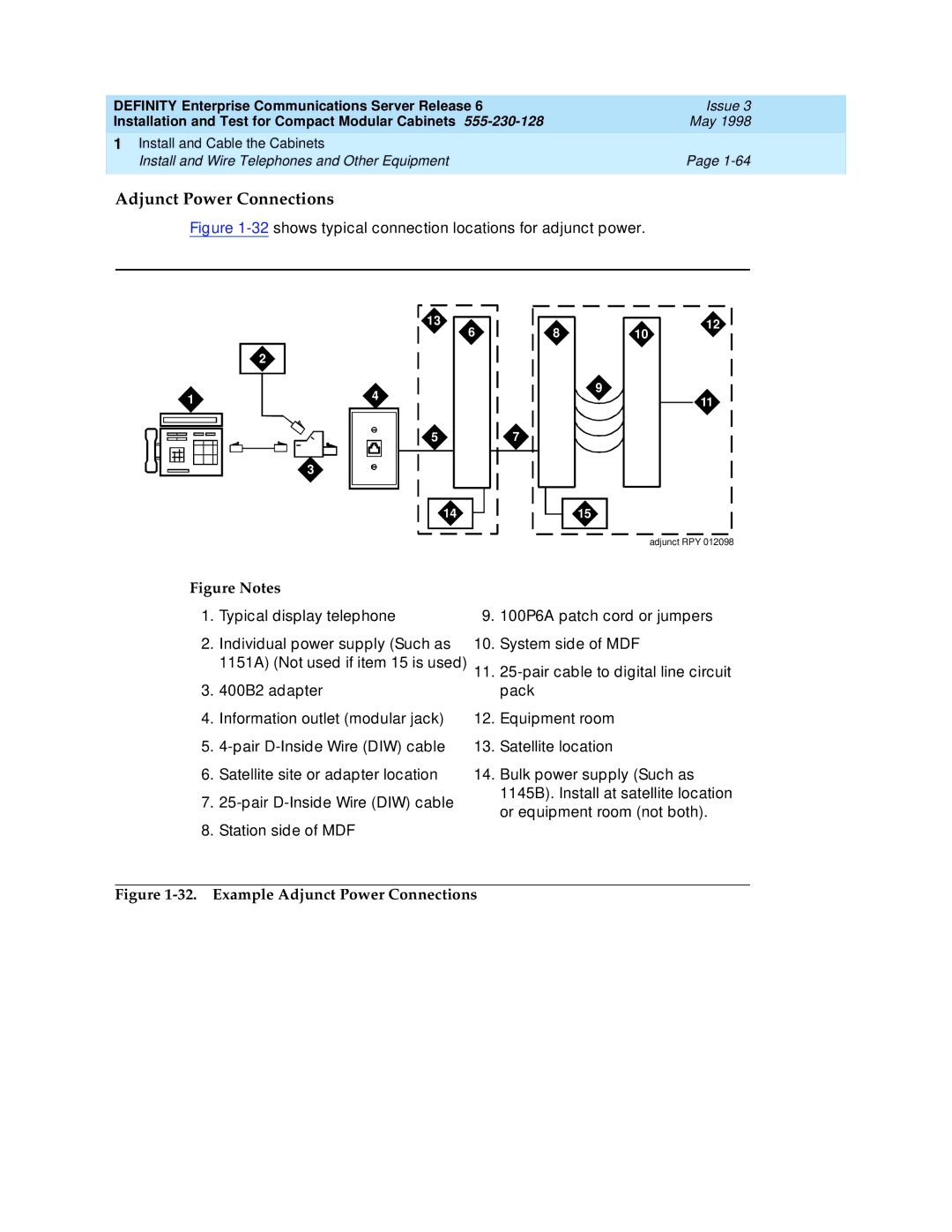
Figure 1-32 shows typical connection locations for adjunct power.
2
4 |
13
6
810
9
12
1 |
3
5
14
11
7
15
adjunct RPY 012098
Figure Notes |
|
| |
1. | Typical display telephone | 9. | 100P6A patch cord or jumpers |
2. | Individual power supply (Such as | 10. | System side of MDF |
| 1151A) (Not used if item 15 is used) | 11. | |
3. | 400B2 adapter |
| pack |
4. | Information outlet (modular jack) | 12. | Equipment room |
5. | 13. | Satellite location | |
6. | Satellite site or adapter location | 14. | Bulk power supply (Such as |
7. |
| 1145B). Install at satellite location | |
| or equipment room (not both). | ||
|
|
| |
8. | Station side of MDF |
|
|
