DEFINITY Enterprise Communications Server Release 6 | Issue 3 |
Installation and Test for Compact Modular Cabinets | May 1998 |
1 Install and Cable the Cabinets |
|
Connect Modem to Telephone Network | Page |
|
|
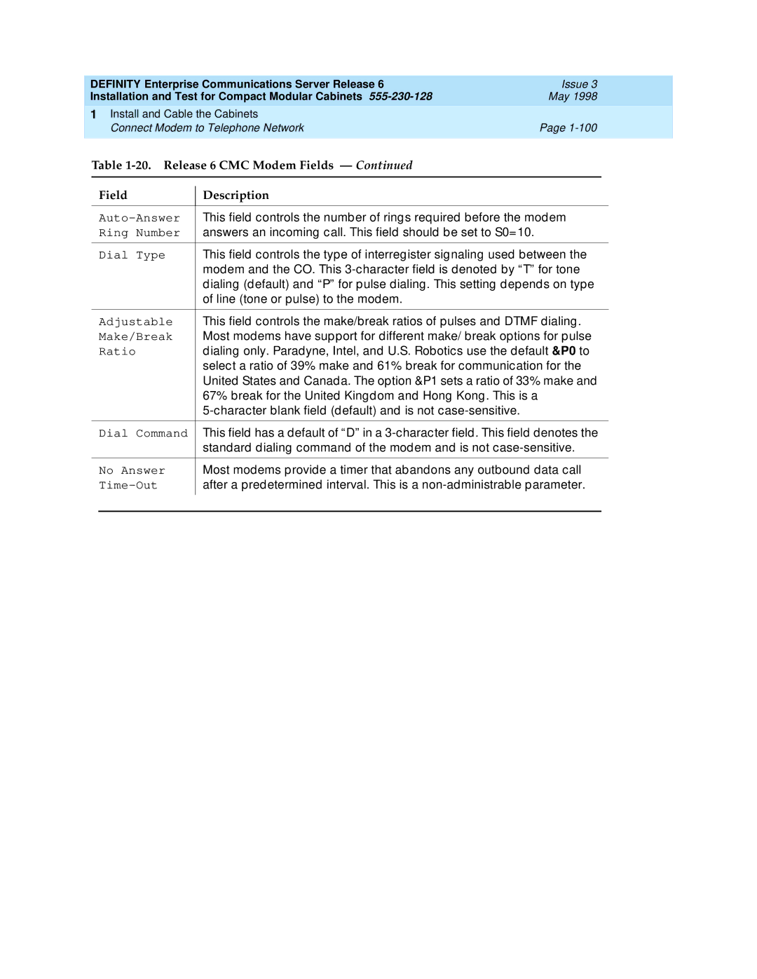
Table 1-20. Release 6 CMC Modem Fields — Continued
Field
Description
| This field controls the number of rings required before the modem | ||
| Ring Number | answers an incoming call. This field should be set to S0=10. | |
|
|
|
|
| Dial Type | This field controls the type of interregister signaling used between the | |
|
| modem and the CO. This | |
|
| dialing (default) and “P” for pulse dialing. This setting depends on type | |
|
| of line (tone or pulse) to the modem. | |
|
|
|
|
| Adjustable | This field controls the make/break ratios of pulses and DTMF dialing. | |
| Make/Break | Most modems have support for different make/ break options for pulse | |
| Ratio | dialing only. Paradyne, Intel, and U.S. Robotics use the default &P0 to | |
|
| select a ratio of 39% make and 61% break for communication for the | |
|
| United States and Canada. The option &P1 sets a ratio of 33% make and | |
|
| 67% break for the United Kingdom and Hong Kong. This is a | |
|
|
| |
|
|
|
|
| Dial Command | This field has a default of “D” in a | |
|
| standard dialing command of the modem and is not | |
|
|
|
|
| No Answer | Most modems provide a timer that abandons any outbound data call | |
| after a predetermined interval. This is a | ||
|
|
|
|
