DEFINITY Enterprise Communications Server Release 6 | Issue 3 |
Installation and Test for Compact Modular Cabinets | May 1998 |
1 Install and Cable the Cabinets |
|
Install Emergency Transfer Unit and Associated Telephones | Page |
|
|
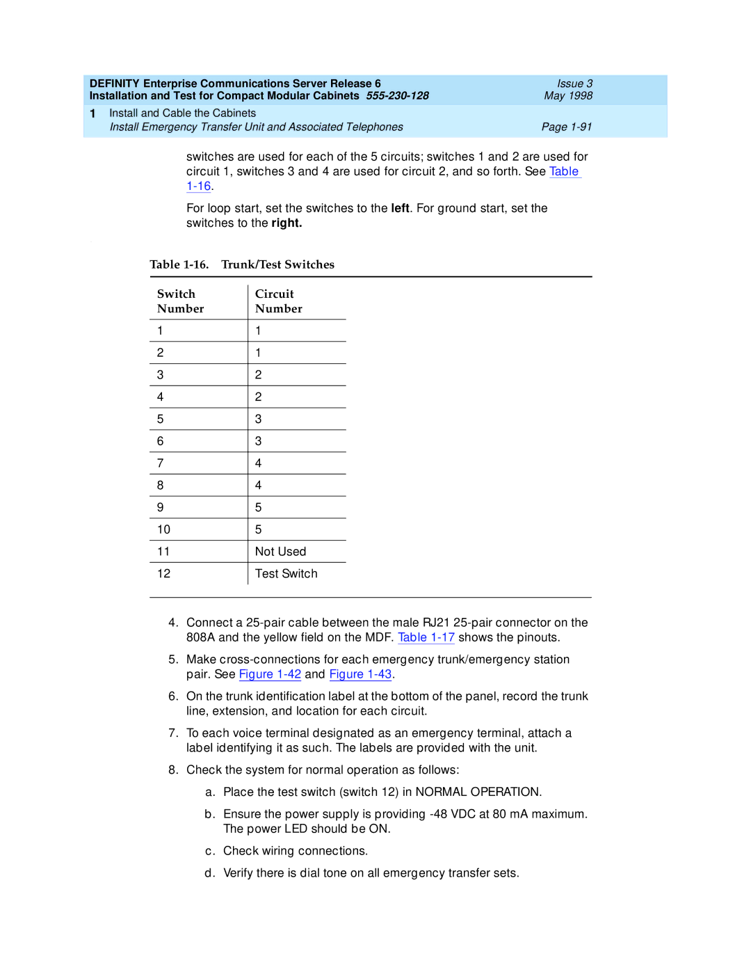
switches are used for each of the 5 circuits; switches 1 and 2 are used for circuit 1, switches 3 and 4 are used for circuit 2, and so forth. See Table
For loop start, set the switches to the left. For ground start, set the switches to the right.
.
Table | Trunk/Test Switches | ||
|
|
|
|
Switch |
| Circuit | |
| |||
Number |
| Number | |
|
|
|
|
1 |
| 1 |
|
|
|
|
|
2 |
| 1 |
|
|
|
|
|
3 |
| 2 |
|
|
|
|
|
4 |
| 2 |
|
|
|
|
|
5 |
| 3 |
|
|
|
|
|
6 |
| 3 |
|
|
|
|
|
7 |
| 4 |
|
|
|
|
|
8 |
| 4 |
|
|
|
|
|
9 |
| 5 |
|
|
|
|
|
10 |
| 5 |
|
|
|
|
|
11 |
| Not Used | |
|
|
|
|
12 |
| Test Switch | |
|
|
|
|
|
|
|
|
4.Connect a
5.Make
6.On the trunk identification label at the bottom of the panel, record the trunk line, extension, and location for each circuit.
7.To each voice terminal designated as an emergency terminal, attach a label identifying it as such. The labels are provided with the unit.
8.Check the system for normal operation as follows:
a. Place the test switch (switch 12) in NORMAL OPERATION.
b. Ensure the power supply is providing
c. Check wiring connections.
d. Verify there is dial tone on all emergency transfer sets.